Debris Filter for Fluidic Measurement with Recess Size Decreasing in Fluid Flow Direction

Active Publication Date: 2014-10-16
AGILENT TECH INC
View PDF4 Cites 7 Cited by
  • Summary
  • Abstract
  • Description
  • Claims
  • Application Information

AI Technical Summary

Benefits of technology

[0039]In an embodiment, the fluidic member is configured as a separation unit, particularly a chromatographic column, configured for separating compounds of the fluid, wherein the filter is arranged at an inlet and/or at an outlet of the separation unit. A chromatographic separation column needs to be fed, at its inlet, with a pure and debris free fluid. Therefore, the inlet of the separation column can be provided with a filter according to an exemplary embodiment of the invention to replace a conventional frit. Additionally or alternatively, the outlet of the column can be provided with a filter according to an exemplary embodiment of the invention so as to prevent separating beads within the column from being flushed out of the chromatographic column. Such an outlet filter may therefore have the function to inhibit flow of beads through the filter which has an impact on the usable pore sizes. Beads for instance may have a dimension of 1.8 μm so that the pores of the filter at the outlet of the separation column should be smaller than this value.
[0040]In an embodiment, the fluidic member is configured as a mobile phase drive, particularly a pumping system, configured to drive the fluid, wherein the filter is arranged at an outlet of the mobile phase drive. In such a high pressure pump, reciprocation of a piston within a seal installed on the piston chamber may result in an abrasion of small particles in the pumping chamber which can then be introduced unintentionally into the fluid. By providing a filter according to an exemplary embodiment at an outlet of such a pumping unit it is possible to prevent debris from entering a connected fluidic path.
[0041]In an embodiment, the fluidic member is configured as a sample injector for injecting the fluid in a sample separation path, wherein the sample injector comprises an injection needle and a seat, wherein the injection needle is selectively insertable into the seat for conducting the fluid between the needle and the seat, wherein the injection needle is selectively movable out of the seat, and wherein the filter is arranged at an outlet of the sa

Problems solved by technology

In such and other fluidic measurement devices, debris can be unintentionally introduced in the processed fluid, for instance due to abrasion of a seal in a piston chamber of a pump, abrasion of a rotatable fluidic valve during switching, solid matter in the matrix of the sample, etc.
However, conve

Method used


Image

  • Debris Filter for Fluidic Measurement with Recess Size Decreasing in Fluid Flow Direction
  • Debris Filter for Fluidic Measurement with Recess Size Decreasing in Fluid Flow Direction
  • Debris Filter for Fluidic Measurement with Recess Size Decreasing in Fluid Flow Direction

Examples


Example

[0066]The illustration in the drawing is schematically.

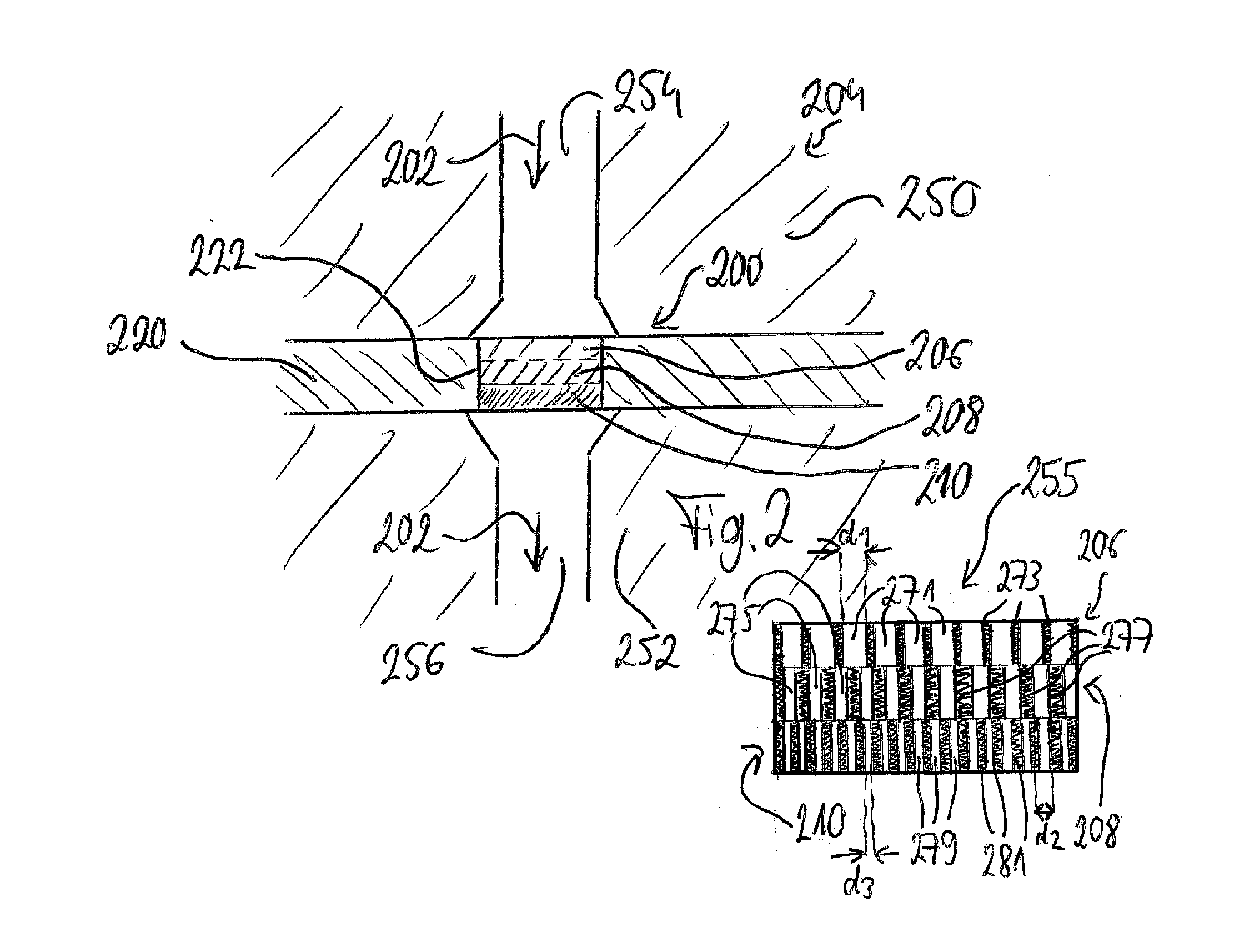
[0067]Embodiments of the invention relate to the filtering of liquid in a three-dimensional structure, particularly implementing a gradually decreasing pore-size in a designed filter. Before exemplary embodiments of the invention will be explained in detail, some basic considerations of the present inventor will be summarized based on which exemplary embodiments of the invention have been developed.

[0068]In gradient Liquid Chromatography (LC) systems often there is a requirement to have both dispensing of clean liquids, while pumping against pressure and still having lowest possible delay volume. Modern UHPLC-systems nowadays have ever increasing requirements. In the interest to increase peak capacity (total number of peaks per time interval) several parameters may be optimized such as smaller size of packing material, smaller columns, faster linear speed of solutes during separation, faster compositional gradients, longer separ...


PUM

PropertyMeasurementUnit
Pore sizeaaaaaaaaaa
Pore sizeaaaaaaaaaa
Pressureaaaaaaaaaa

Abstract

A filter for filtering debris out of a fluid flowing along a fluid flow direction in a fluidic member of a sample separation device, the filter comprising a plurality of filter structures stacked along the fluid flow direction and each having pores with defined pore size, wherein the defined pore size of the stacked filter structures decreases along the fluid flow direction.

Description

BACKGROUND ART[0001]The present invention relates to a filter, a fluidic member, a sample separation device, and a method of manufacturing a filter.[0002]In liquid chromatography, a fluidic sample and an eluent (liquid mobile phase) may be pumped, by a piston pump, through conduits and a column in which separation of sample components takes place. In a sample loop, the sample may be injected into a fluidic path by a mechanically drivable needle. The drivable needle is controllable to be moved out of a seat of the sample loop into a vial to receive a fluid and back from the vial into the seat. The column may comprise a material which is capable of separating different components of the fluidic analyte. Such a material, so-called beads, which may comprise silica gel, may be filled into a column tube which may be connected downstream to other components, such as a detector, a fractioner, a waste, etc., by conduits.[0003]In such and other fluidic measurement devices, debris can be unint...

Claims


Application Information

Patent Timeline
IPC IPC(8): G01N1/20B01D39/14
CPCB01D39/00B01D39/10B01D2239/065G01N1/20B01D2239/1216B01D39/14B01D2239/069G01N30/603
Inventor WITT, KLAUSHAERTL, HANS-GEORG
Owner AGILENT TECH INC
Why Eureka
Try Eureka