
Ophthalmologic apparatus, method for controlling ophthalmologic apparatus, and program

a technology of ophthalmologic equipment and ophthalmologic fundus, which is applied in the field of ophthalmologic equipment, methods for controlling ophthalmologic equipment, and programs, can solve the problems of difficult to quickly capture an image of the eye fundus to be examined, unsuitable working distance, and inability to determine an examiner

Active Publication Date: 2014-10-16
CANON KK
View PDF1 Cites 13 Cited by
  • Summary
  • Abstract
  • Description
  • Claims
  • Application Information

AI Technical Summary

Benefits of technology

This patent describes an eye examination apparatus that uses an optical unit to capture images of the eye, a target projection unit to adjust the distance between the eye and the optical unit, and a determination unit to decide whether the distance is suitable based on an image of the cornea reflection. The apparatus can automatically adjust the direction in which the distance is adjusted to ensure that the target is in focus using the information in the cornea reflection image. The technical effect of this invention is to improve the accuracy and efficiency of eye examinations by automating the process of adjusting the working distance between the eye and the optical unit based on the cornea reflection image.

Problems solved by technology

It is difficult, however, for an examiner to determine whether the working distance between the eye to be examined and the ophthalmologic apparatus is greater or less than an appropriate working distance at a point at which the examiner is trying to adjust the working distance while observing a reflection image of a target on a monitor.
Thus, the examiner simply determines that the working distance is not appropriate in a state in which the target is out of focus while observing the reflection image of the target projected on the monitor and moves the apparatus body back and forth in the optical axis direction.
Accordingly, it is difficult to promptly capture an image of the fundus of the eye to be examined.

Method used


Image

  • Ophthalmologic apparatus, method for controlling ophthalmologic apparatus, and program
  • Ophthalmologic apparatus, method for controlling ophthalmologic apparatus, and program
  • Ophthalmologic apparatus, method for controlling ophthalmologic apparatus, and program

Examples


Embodiment Construction

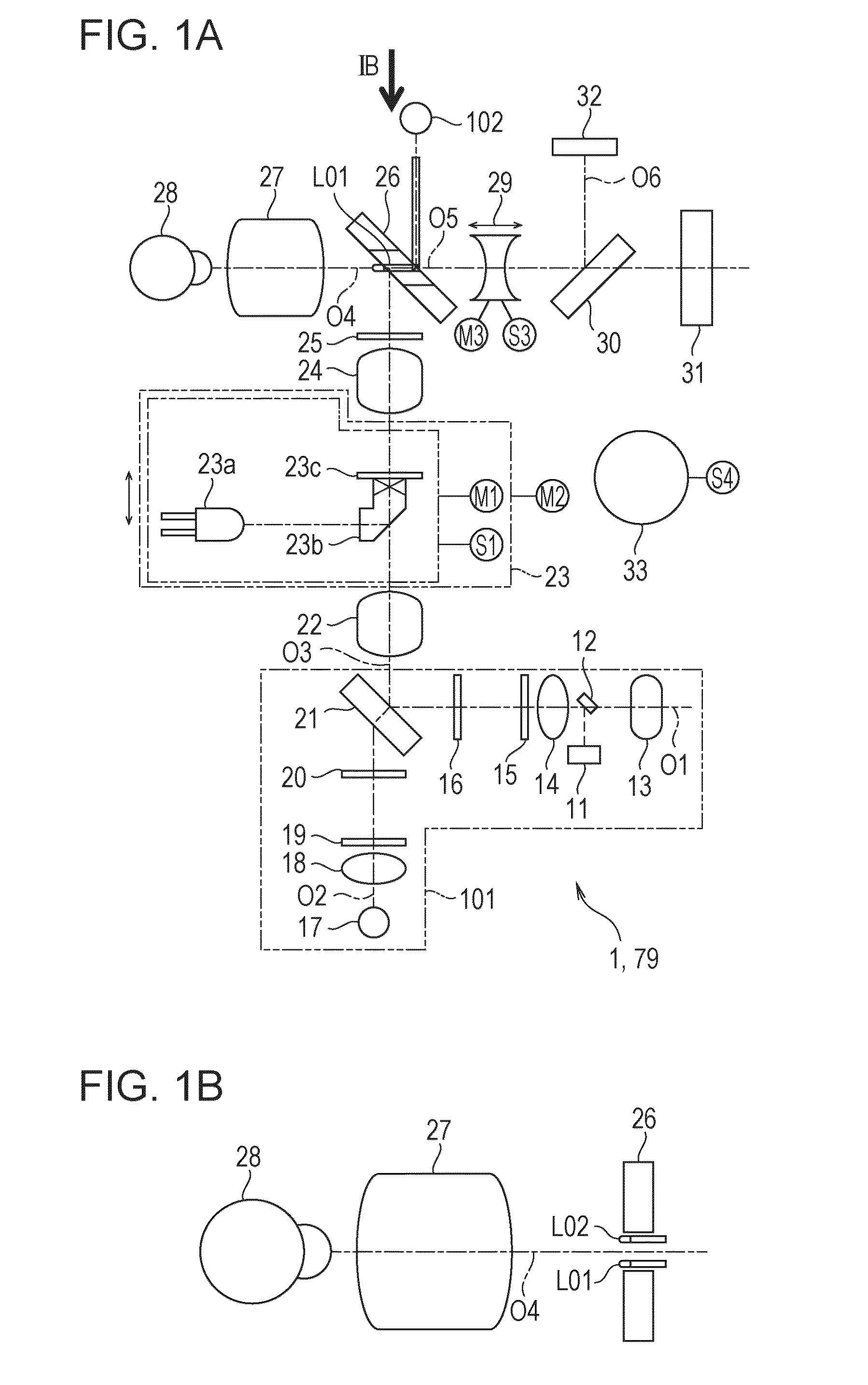
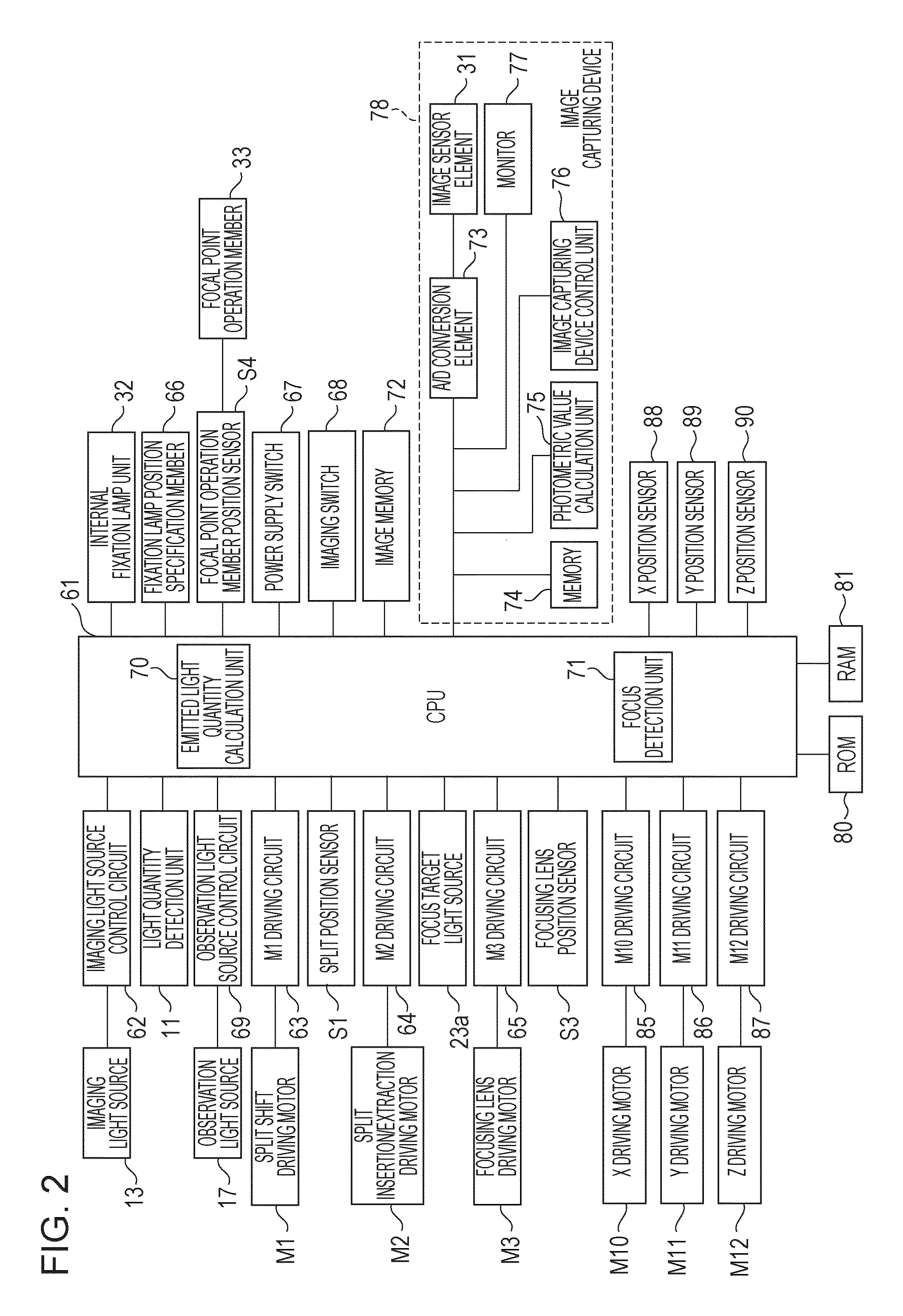
[0023]Hereinafter, an ophthalmologic apparatus according to an exemplary embodiment will be described in detail with reference to FIGS. 1A to 13. A fundus camera is illustrated as the ophthalmologic apparatus according to the exemplary embodiment. The ophthalmologic apparatus according to the exemplary embodiment, however, is not limited to the fundus camera. The exemplary embodiment can be applied to various other ophthalmologic apparatuses such as various types of ophthalmologic photographing apparatuses and ocular refractivity measurement apparatuses.

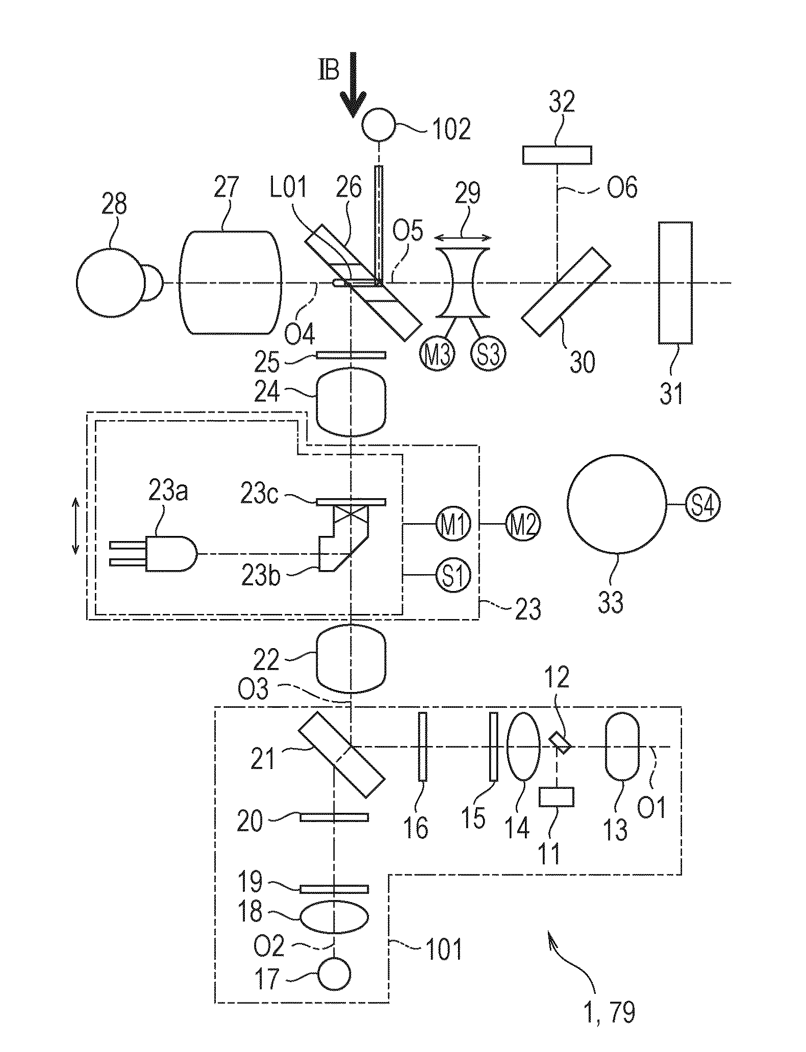
[0024]First, with reference to FIGS. 1A and 1B, a general configuration of a fundus camera 1, which serves as the ophthalmologic apparatus according to the exemplary embodiment, will be described. FIGS. 1A and 1B schematically illustrate the general configuration of the fundus camera 1.

[0025]The fundus camera 1 includes an imaging light source section O1, an observation light source section O2, an illumination optical system O3, an i...


PUM


Abstract

An ophthalmologic apparatus is configured to determine a direction in which a target that is used to adjust a working distance comes into focus based on an influence of astigmatism contained in a cornea reflection image of an eye to be examined.

Description

BACKGROUND[0001]1. Field[0002]Aspects of the present invention generally relate to ophthalmologic apparatuses, methods for controlling ophthalmologic apparatuses, and programs.[0003]2. Description of the Related Art[0004]Among existing ophthalmologic apparatuses, in a fundus camera, for example, a working distance between an eye to be examined and the ophthalmologic apparatus in an optical axis direction is adjusted to an appropriate distance prior to capturing an image of a fundus of the eye to be examined. In one of the known methods for adjusting the working distance, a cornea reflection image of a target that has been projected on a cornea of an eye to be examined is observed on a monitor, and the target is manually brought into focus. In addition, known is a configuration in which an ophthalmologic apparatus automatically determines whether the working distance is appropriate based on information on a luminance value distribution of a cornea reflection image of a target that ha...

Claims


Application Information

Patent Timeline
IPC IPC(8): A61B3/15A61B3/12
CPCA61B3/12A61B3/154
Inventor OHBAN, HIDEYUKI
Owner CANON KK
Learn More