
Ophthalmic apparatus

a technology of ophthalmic apparatus and working distance, applied in the field of ophthalmic apparatus, can solve the problems of short working distance of ophthalmic apparatus and complicated structure, and achieve the effect of reducing the size of ophthalmic apparatus

Inactive Publication Date: 2010-01-19
KK TOPCON
View PDF3 Cites 0 Cited by
  • Summary
  • Abstract
  • Description
  • Claims
  • Application Information

AI Technical Summary

Benefits of technology

The present invention provides a device for measuring the shape of the cornea of the eye without causing instrument myopia and regardless of the shape of the pattern member. The device uses an ophthalmic apparatus with a projection system and an optical observation system. The pattern member is coated with a paint that transmits infrared light and blocks visible light, preventing the subject from seeing the predetermined pattern. The eye of the subject is observed by the light reflected by the cornea, and the surface of the pattern member is coated with a paint that blocks visible light. The invention allows for the measurement of the eye with a minimum structure and reduces the size of the ophthalmic apparatus.

Problems solved by technology

In a conventional ophthalmic apparatus, a filter that transmits infrared light but blocks visible light is disposed between a pattern plate and a subject, whereby the pattern plate and the filter are required to have the same shape, and the structure is complicated.
Moreover, a filter must be disposed between a pattern plate and a subject, and the working distance of an ophthalmic apparatus is thereby somewhat short.

Method used


Image

  • Ophthalmic apparatus
  • Ophthalmic apparatus
  • Ophthalmic apparatus

Examples


Embodiment Construction

[0031]An example of an ophthalmic apparatus together with an apparatus for measuring the shape of the cornea according to the present invention will be described hereinbelow with reference to the figures.

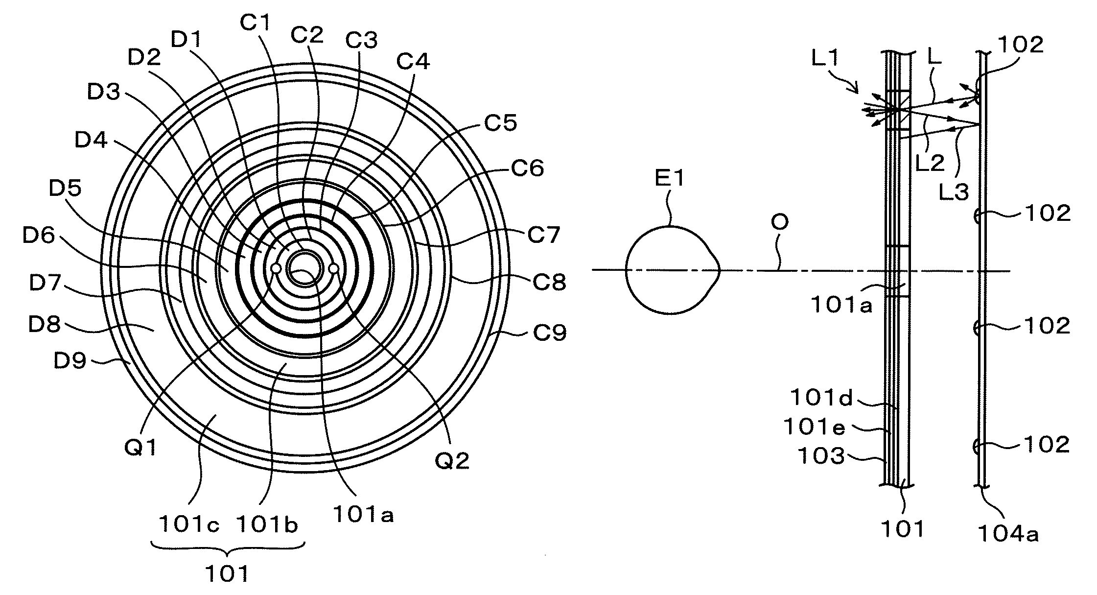
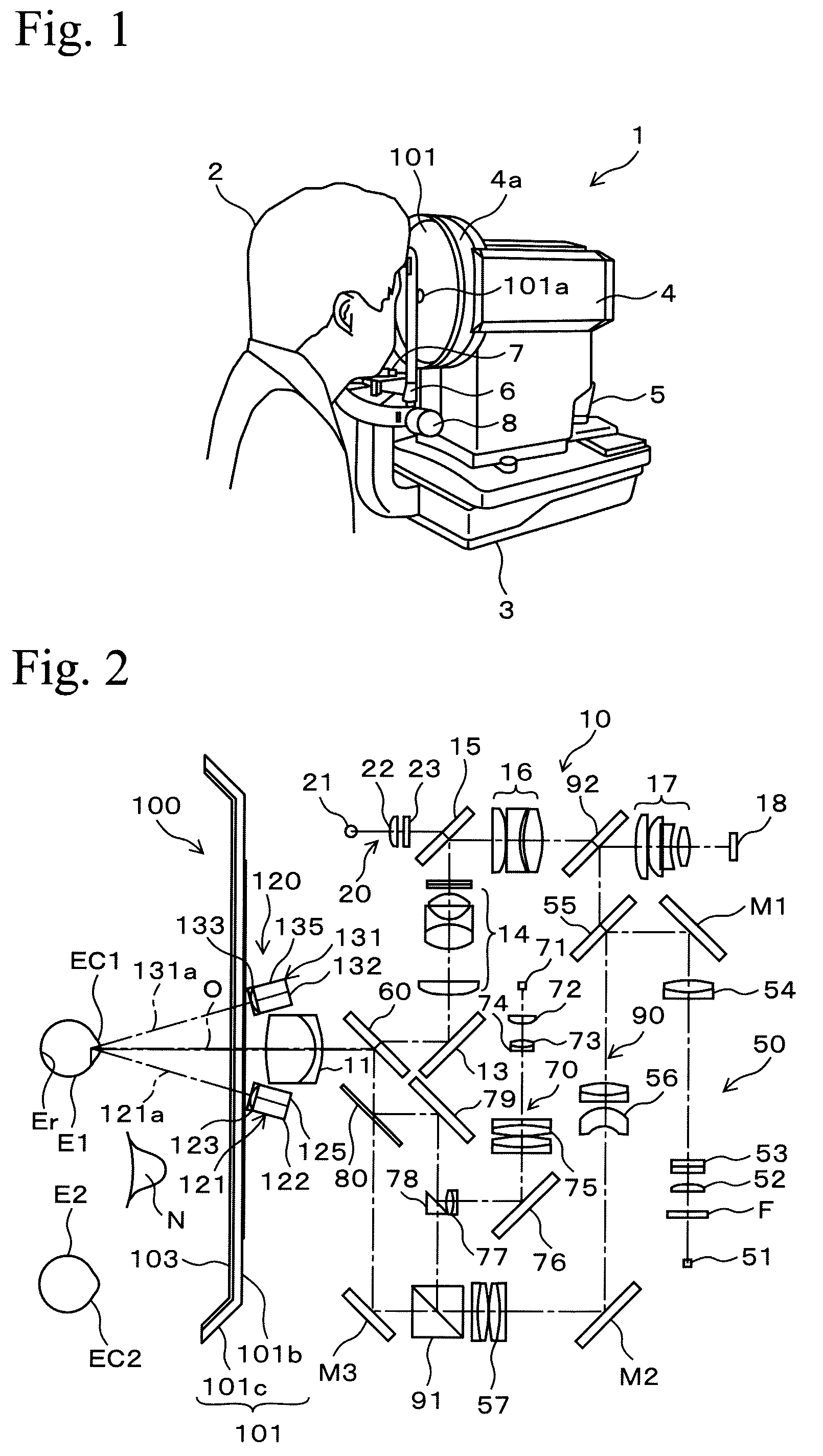
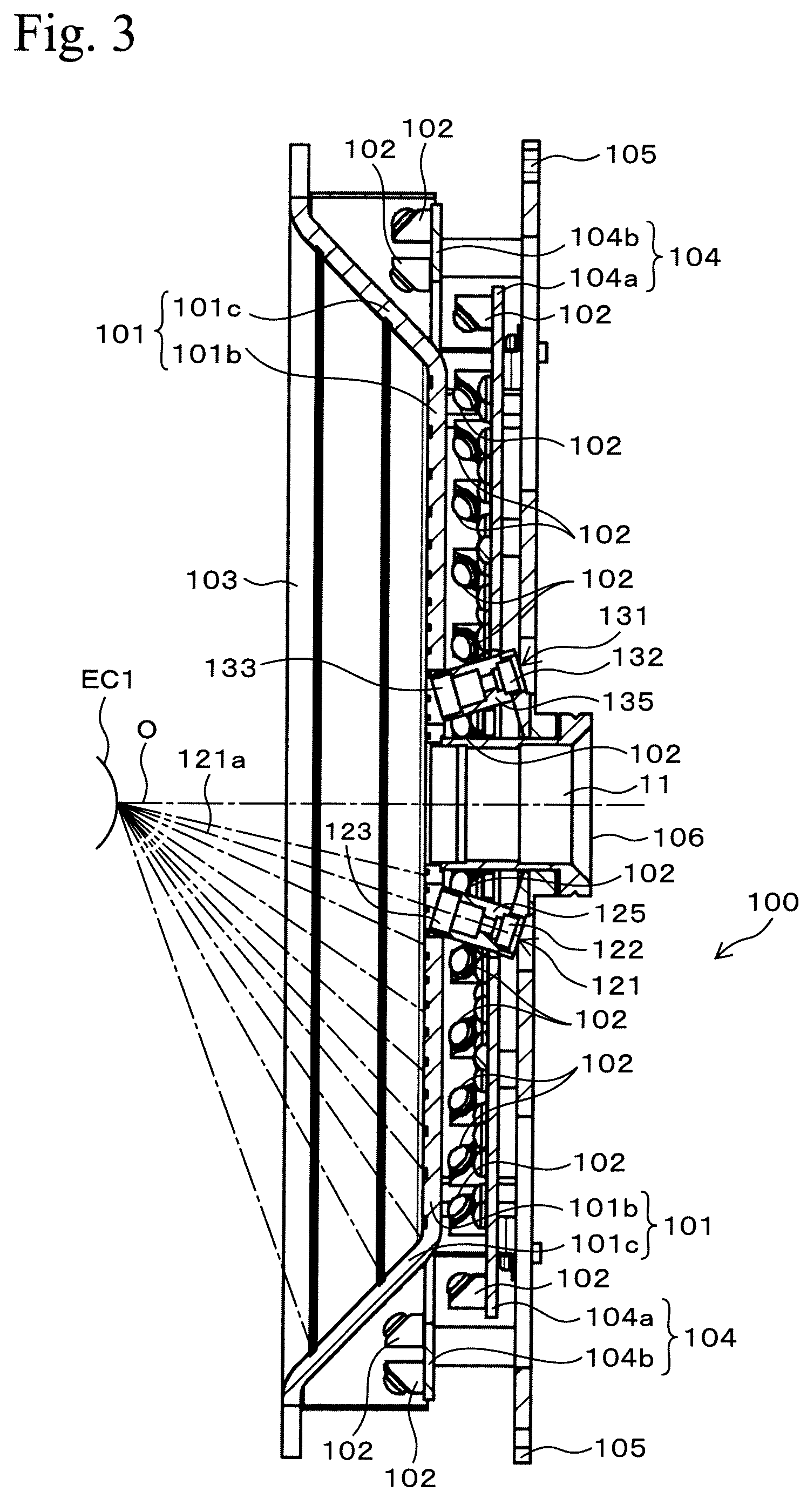
[0032]FIG. 1 is a perspective view showing the relationship of an ophthalmic apparatus according to the present invention and a subject. FIG. 2 is an optical layout drawing showing a layout of an optical system of an ophthalmic apparatus. FIG. 3 is a sectional view showing a structure of a placido pattern projecting system. FIG. 4 is a front view showing a pattern portion of a placido pattern projecting system. FIG. 5 is a front view of a holding plate showing an arrangement of infrared light-emitting diodes. FIGS. 6A and 6B are explanatory drawings showing differences in positions of patterns and differences in sizes of pattern portions due to the shape of the pattern portion. FIGS. 7A and 7B are schematic drawings showing portions of a placido pattern projecting system enlarged. F...


PUM


Abstract

An ophthalmic apparatus comprises a projection system in which a pattern member is provided with a predetermined pattern for measuring the shape of the cornea of an eye of a subject, the predetermined pattern is thereby projected on the cornea of the eye of the subject, and an optical observation system in which light flux having a shape of the predetermined pattern emitted from the projection system is reflected at the cornea of the eye of the subject, the eye of the subject is observed by the light reflected by the cornea. A surface at the eye of the subject side of the pattern member is coated with a paint having a filtering property that transmits infrared light and blocks visible light.

Description

REFERENCE TO THE RELATED APPLICATIONS[0001]This application claims priority under 35 U.S.C. §119 to Japanese Patent Application No. JP2007-074327 filed Mar. 22, 2007, the entire content of which is hereby incorporated by reference.BACKGROUND[0002]1. Technical Field[0003]The present invention relates to an ophthalmic apparatus for measuring the shape of the cornea of the eye of a subject.[0004]2. Background Information[0005]Conventionally, in an ophthalmic apparatus for precisely measuring the shape of the cornea, concentric light transmitting portions, that is, light transmitting ring patterns (a placido pattern) are provided to a flat pattern plate, and plural light sources are arranged along the light transmitting ring pattern on a holding plate behind the pattern plate. The light source emits infrared light. This is because infrared light does not cause pupil contraction of the eye of the subject which would occur if a light transmitting ring pattern were projected in visible lig...

Claims


Application Information

Patent Timeline
Patent Type & Authority Patents(United States)
IPC IPC(8): A61B3/10
CPCA61B3/107
Inventor NAKAZAWA, NAOKINAKAJIMA, KOJIMIHASHI, TOSHIFUMI
Owner KK TOPCON
Learn More