Method of verifying performance of an optical measurement instrument with a model eye and an optical measurement instrument employing such a method

a technology of optical measurement instruments and model eyes, applied in the field of optical measurement instruments, can solve the problems of adding expense to the model eye mount, difficult and/or time-consuming for the operator, and difficult to verify the operation of the optical measurement instrumen

Active Publication Date: 2014-05-20
AMO DEVMENT
View PDF25 Cites 0 Cited by
  • Summary
  • Abstract
  • Description
  • Claims
  • Application Information

AI Technical Summary

Benefits of technology

[0009]In contrast to this simple method of aligning a human eye by means of a fixation target, it may be difficult and / or time-consuming for an operator through trial-and-error to achieve a degree of alignment between a model eye and the optical measurement instrument's optical axis that renders insignificant the variation in the measured sphere and / or cylinder. One solution is to constrain the model eye by mechanical means so it points directly toward the optical measurement instrument. However, this approach adds expense to the model eye mount and may not reduce the measurement variation to within a desired tolerance.
[0010]Therefore, it would be desirable to provide a method of verifying proper operation with an optical measurement instrument with a model eye that can address variations in measurements that occur when the model eye is misaligned with respect to the optical measurement instrument. It would also be desirable to provide an optical measurement instrument that can operate with such a method.

Problems solved by technology

This variation in the measured sphere and / or cylinder values that depends on the misalignment angle between the optical measurement instrument and the model eye makes it hard to verify proper operation of the optical measurement instrument.
In contrast to this simple method of aligning a human eye by means of a fixation target, it may be difficult and / or time-consuming for an operator through trial-and-error to achieve a degree of alignment between a model eye and the optical measurement instrument's optical axis that renders insignificant the variation in the measured sphere and / or cylinder.
However, this approach adds expense to the model eye mount and may not reduce the measurement variation to within a desired tolerance.

Method used


Image

  • Method of verifying performance of an optical measurement instrument with a model eye and an optical measurement instrument employing such a method
  • Method of verifying performance of an optical measurement instrument with a model eye and an optical measurement instrument employing such a method
  • Method of verifying performance of an optical measurement instrument with a model eye and an optical measurement instrument employing such a method

Examples


Embodiment Construction

[0022]Exemplary embodiments of model eyes and methods for verifying proper operation and performance of optical measurement equipment through use of a model eye will be described in some detail below so as to illustrate various aspects and advantages of these devices and methods. However, it should be understood that the principles involved in these devices and methods can be employed in a variety of other contexts, and therefore the novel devices and method disclosed and claimed here should not be construed as being limited to the example embodiments described below.

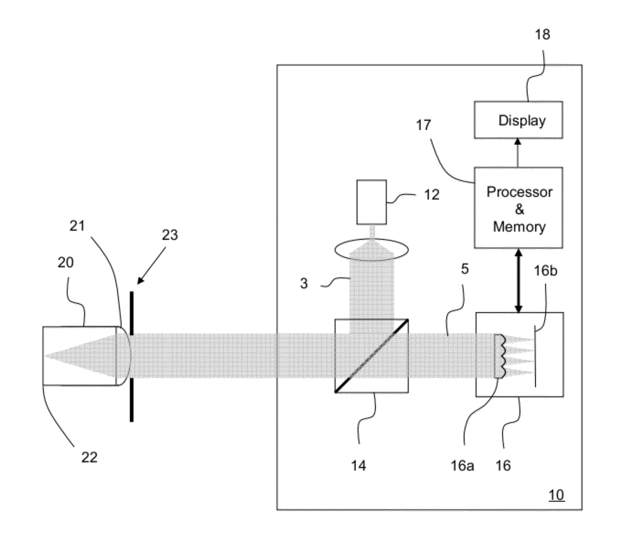
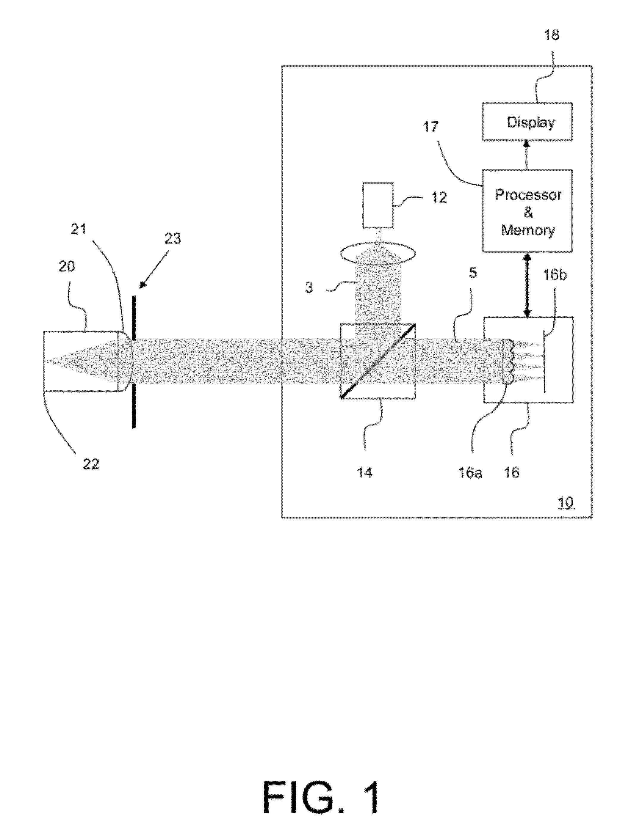
[0023]FIG. 1 illustrates an example embodiment of an optical measurement instrument 10 making a measurement with an example embodiment of a model eye 20 to verify correct operation and specified performance of an optical measurement instrument. Here optical measurement instrument 10 may be a wavefront aberrometer. Optical measurement instrument 10 includes, among other elements, a coherent light source (e.g., a laser or...


PUM


Abstract

A method of compensating for misalignment between an optical measurement instrument and a model eye includes: receiving a light beam from the model eye at the optical measurement instrument; producing image data, including light spot data for a plurality of light spots, from the received light beam; determining an observed location of a corneal reflex from the model eye within an image representing the image data; and determining an angle of misalignment between an axis normal to the front surface of the model eye and the optical axis of the optical measurement instrument from the observed location of the corneal reflex within the image.

Description

CROSS-REFERENCES TO RELATED APPLICATION[0001]This application claims priority to U.S. Provisional Application No. 61 / 490,139, filed on May 26, 2011, the entirety of which is hereby incorporated by reference.BACKGROUND AND SUMMARY[0002]1. Field[0003]This invention pertains to optical measurement instruments, and in particular a method of verifying the correct operation of an optical measurement instrument by using a model eye, and an optical measurement instrument that employs such a method.[0004]2. Description[0005]It is sometimes necessary to be able to verify correct operation and specified performance of an optical measurement instrument such as a wavefront aberrometer in an operational setting. In many instances, this is done by operating the optical measurement instrument to make a measurement of a model eye whose characteristics are known. A common version of a model eye is a solid glass or plastic component with a curved front surface and a flat back surface. The front curve ...

Claims


Application Information

Patent Timeline
Patent Type & Authority Patents(United States)
IPC IPC(8): G01B11/26
CPCA61B3/152G01B11/26G01M11/00
Inventor COPLAND, JAMES
Owner AMO DEVMENT
Why Eureka
Try Eureka