High-pressure pump, in particular for a fuel injection system of an internal combustion engine

a high-pressure pump and fuel injection technology, which is applied in the direction of machines/engines, liquid fuel engines, positive displacement liquid engines, etc., can solve the problems of high pressure on the pump housing, high cost of high-pressure pumps, and complicated hardening treatment of the pump housing

Inactive Publication Date: 2006-01-12
ROBERT BOSCH GMBH
View PDF4 Cites 2 Cited by
  • Summary
  • Abstract
  • Description
  • Claims
  • Application Information

AI Technical Summary

Problems solved by technology

At high pressures, of the kind required for fuel injection systems for achieving high performance and low pollutant emissions in internal combustion engines, this puts high

Method used


Image

  • High-pressure pump, in particular for a fuel injection system of an internal combustion engine
  • High-pressure pump, in particular for a fuel injection system of an internal combustion engine
  • High-pressure pump, in particular for a fuel injection system of an internal combustion engine

Examples


Embodiment Construction

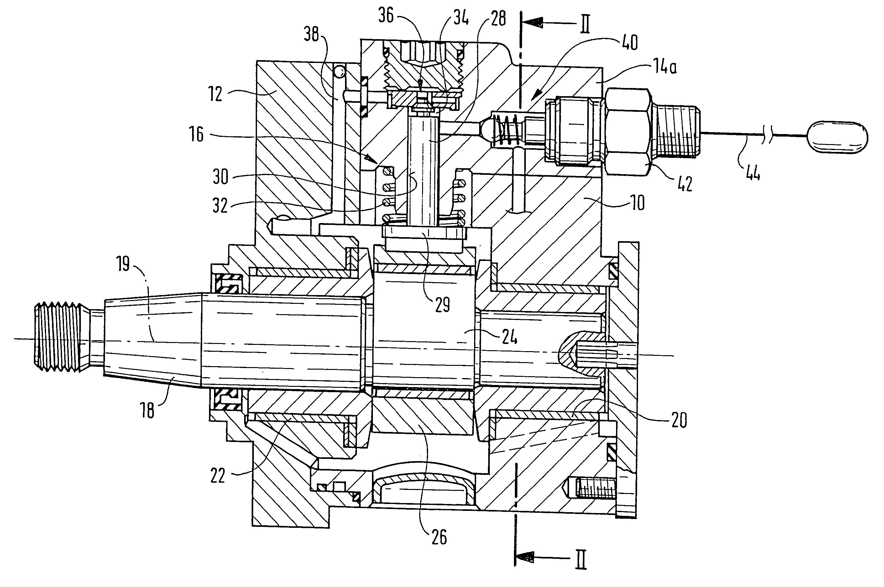
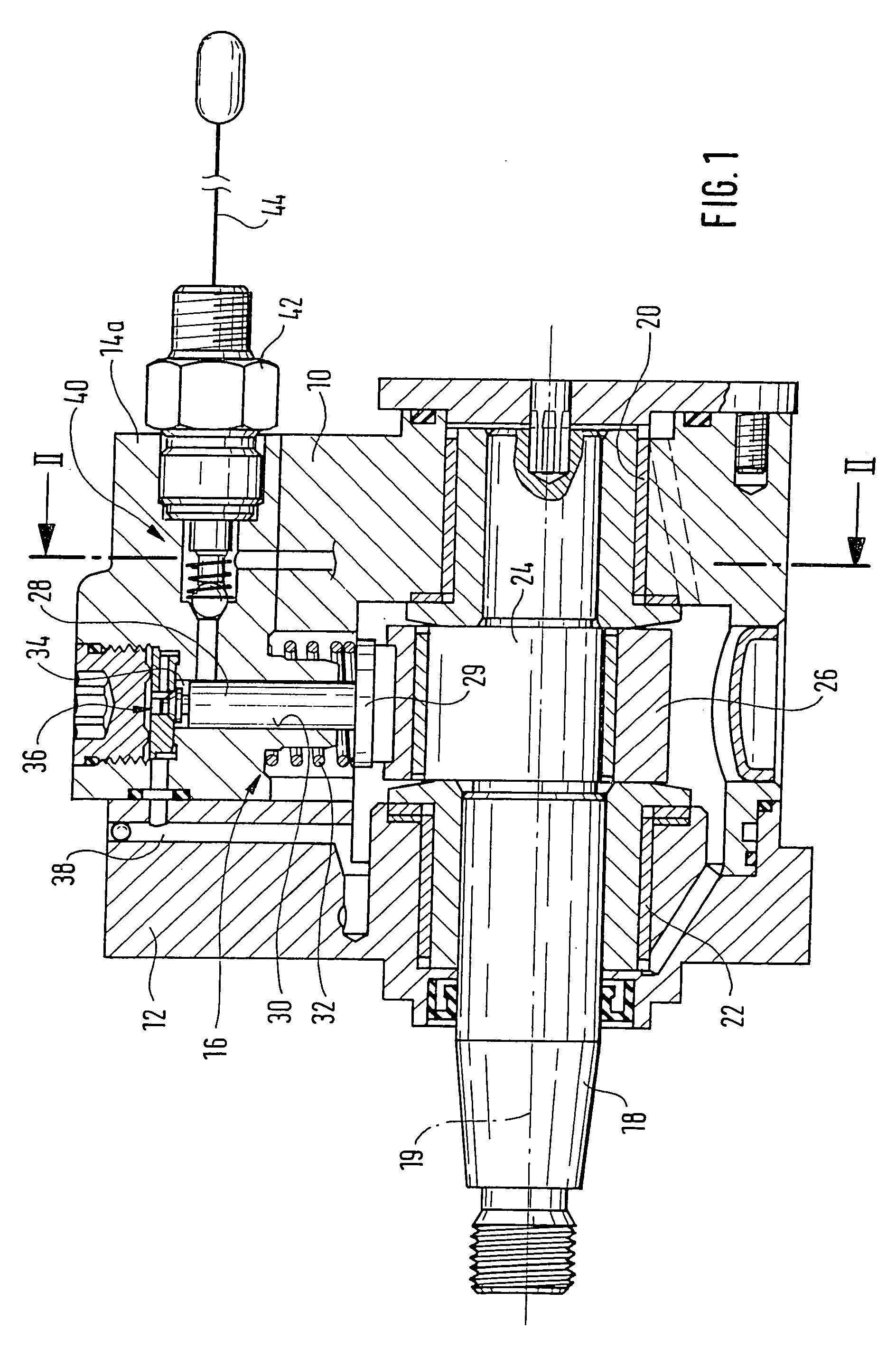
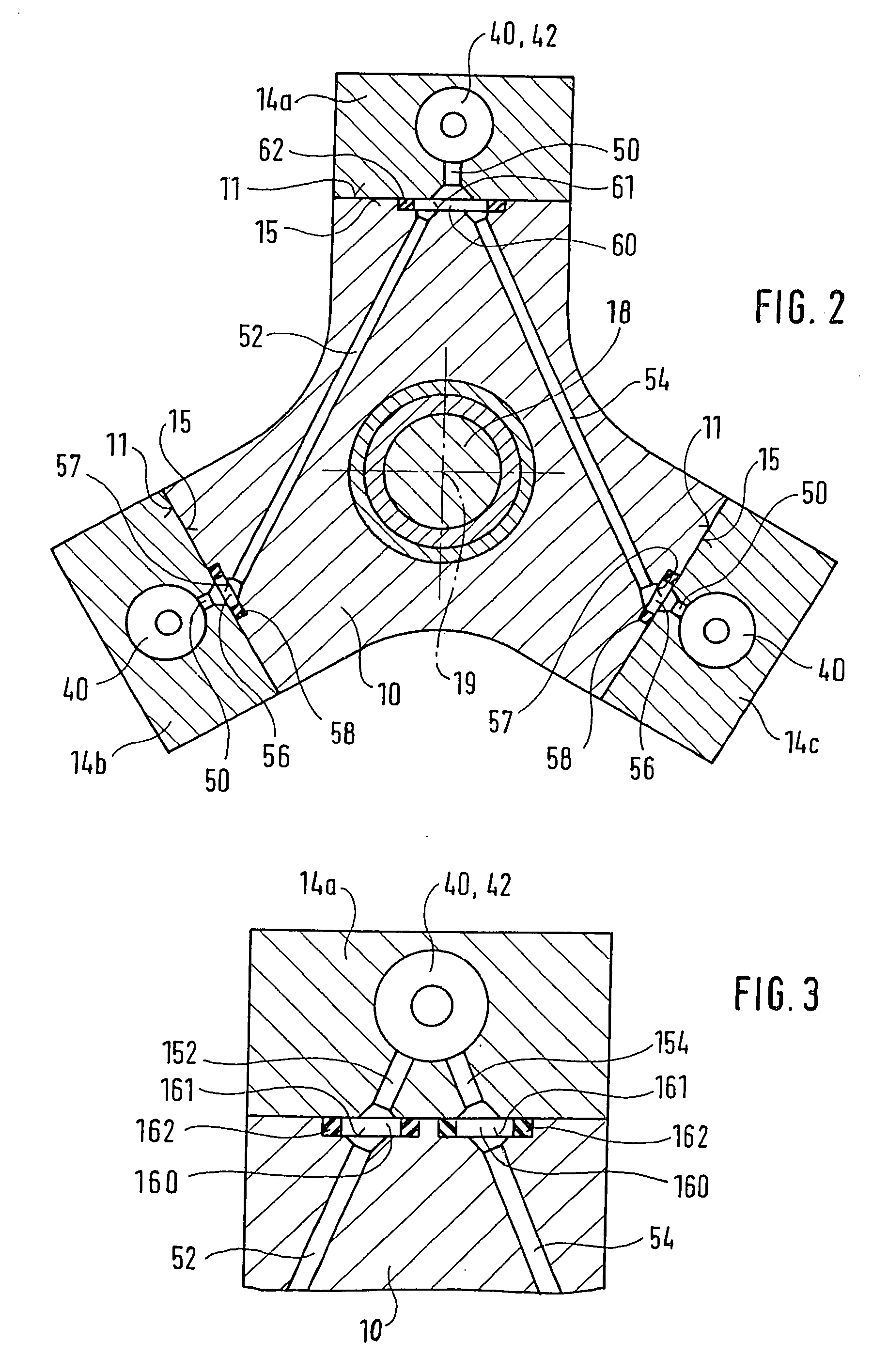
[0009] In FIGS. 1 through 3, a high-pressure pump is shown which is intended in particular for a fuel injection system for an internal combustion engine, for instance of a motor vehicle. By means of the high-pressure pump, fuel is pumped at high pressure of up to 2000 bar, for instance into a reservoir from which fuel is drawn for injection into the engine. The high-pressure pump has a multiple-part pump housing, which has a housing body 10, a flange part 12, and housing caps 14 that are joined to the housing body 10. A plurality of pump elements, for instance three, distributed uniformly over the circumference are disposed in the pump housing. A drive shaft 18 is rotatably supported in the housing body 10 and the flange part 12 and by means of it the pump elements 16 are driven. The drive shaft 18 is rotatably supported about an axis 19 via a bearing point 20 in the housing body 10 and via a bearing point 22 in the flange part 12 and is driven by the engine in a manner not shown. T...


PUM


Abstract

A high-pressure pump having a pump housing in which a plurality of pump elements are disposed, and by means of which fluid is pumped at high pressure via a high-pressure conduit system to a common high-pressure connection. The pump housing has a housing body and for each pump element one housing cap covering the pump element and joined to the housing body. The high-pressure conduit system has high-pressure bores extending without intersections in the housing body which bores are joined together in the region of the transition from the housing body to one of the housing caps, or in one of the housing caps, to form the common high-pressure connection.

Description

PRIOR ART [0001] The invention is based on a high-pressure pump, in particular for a fuel injection system for an internal combustion engine, as generically defined by the preamble to claim 1. [0002] One such high-pressure pump is known from German Patent Disclosure DE 198 02 476 A1. This high-pressure pump has a pump housing in which a plurality of pump elements are disposed. By means of the pump elements, fuel is pumped via a high-pressure conduit system to a common high-pressure connection. The pump housing of the high-pressure pump is embodied in one piece, and the high-pressure conduit system has high-pressure bores, which extend through the pump housing and discharge into one another and thus form intersections. At high pressures, of the kind required for fuel injection systems for achieving high performance and low pollutant emissions in internal combustion engines, this puts high loads on the pump housing. The intersections of the high-pressure bores create peak stresses in ...

Claims


Application Information

Patent Timeline
IPC IPC(8): F04B1/04F04B27/04F02M59/06F02M59/08F04B53/00F04B53/16
CPCF02M59/06F02M59/08F04B53/16F04B53/007F04B1/0404
Inventor BOOS, BURKHARD
Owner ROBERT BOSCH GMBH
Why Eureka
Try Eureka