Lift for a bicycle rack or luggage rack

a technology for lifting a bicycle and a luggage rack, which is applied in the direction of transportation items, load transportation vehicles, supplementary fittings, etc., can solve the problems of difficult lifting of bicycles on and off bicycle racks, difficult lifting of bicycles for loading and unloading on fixed bicycle racks, etc., and achieves greater freedom of choice of mounting locations of lifts. , the effect of greater freedom

Inactive Publication Date: 2014-10-16
BRUSTOR
View PDF6 Cites 11 Cited by
  • Summary
  • Abstract
  • Description
  • Claims
  • Application Information

AI Technical Summary

Benefits of technology

[0022]According to another preferred characteristic the bicycle rack or luggage rack is height adjustable with respect to the carriage, which allows greater freedom for its mounting with regard to the mounting height of the lift.
[0023]An even greater freedom of choice of the mounting locations of the lift can be obtained when the frame for mounting the lift against the vehicle is adjustable in length.

Problems solved by technology

To load and unload the bicycles, they must be lifted on and off the bicycle rack which can sometimes be difficult.
However, such bicycles are relatively heavy, which makes the lifting for loading and unloading on a fixed bicycle rack particularly difficult, especially for older people who nowadays increasingly enjoy convenience, and above all when the bicycle rack is mounted reasonably high up in order to be out of the way.
A disadvantage of such a known bicycle rack is that the vertical travel of the bicycle rack is limited.
This also implies that in the highest position of the lift, the bicycles are suspended quite low, which is not conducive to safety during driving, and increases the potential risk of theft.
Such a lift also sometimes forms an obstacle to access to the luggage or engine compartment, or presents an obstruction to the view through a window or an obstruction to the view of the number plate and indicator lighting, such that extra facilities are needed for auxiliary lights and an extra number plate that is then mounted on the bicycle rack.
Moreover, it is not always possible to mount such a bicycle rack in the most suitable place on account of the presence of a bumper, a window, a door, a spare wheel or similar.

Method used


Image

  • Lift for a bicycle rack or luggage rack
  • Lift for a bicycle rack or luggage rack
  • Lift for a bicycle rack or luggage rack

Examples


Embodiment Construction

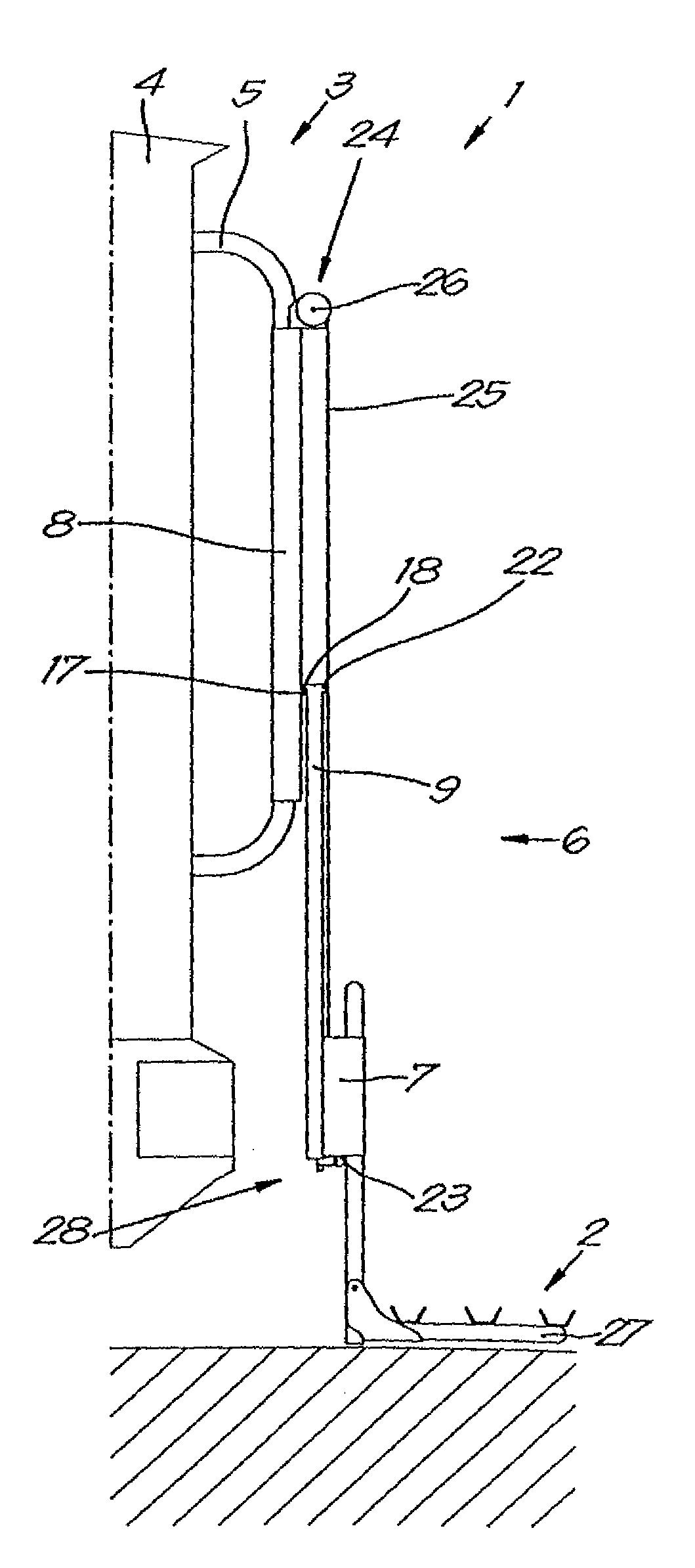
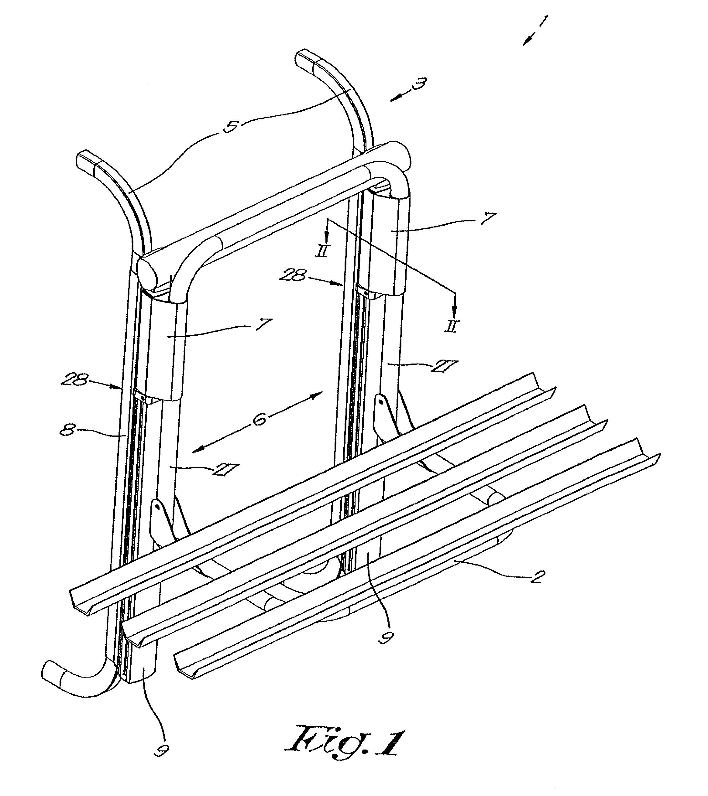
[0034]The lift 1 shown in FIG. 1 is provided with a bicycle rack 2 by way of an example, but alternatively can also be provided with a load platform or box for luggage.

[0035]The lift 1 is provided with a frame 3 for mounting on a motor home 4 or similar, as shown in FIG. 2.

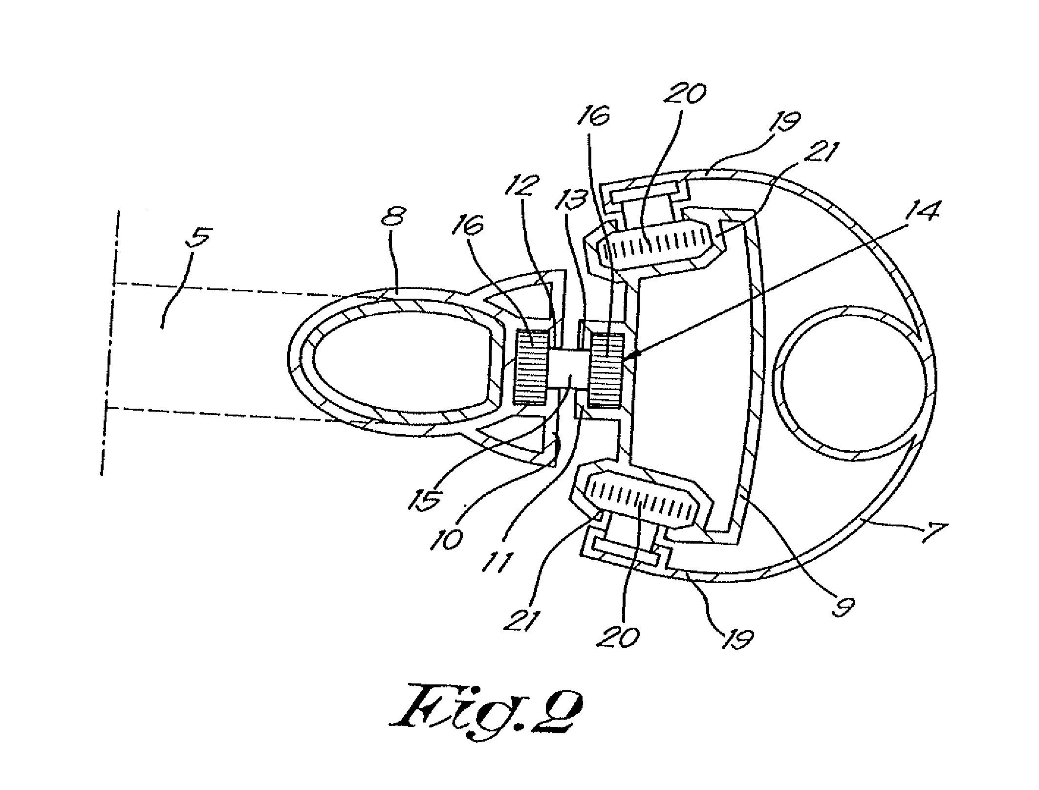
[0036]In this case, this frame 3 is formed by two brackets 5 with an essentially vertically oriented guide 6 on each bracket 5 for a carriage 7 that is height adjustable on the guide 6 and to which the bicycle rack 3 is fastened.

[0037]Each guide 6 is composed of two parallel parts of practically the same length, respectively a fixed part 8 that is fastened to the frame 3 and a movable part 9 that is movable in the longitudinal direction with respect to the fixed part 8 in order to make the guide longer or shorter between a situation of minimum length A in which both parts 8 and 9 are completely slid together, as shown in FIGS. 1 and 3, and a situation of maximum length B whereby the two parts 8 and 9 are slid out ...


PUM


Abstract

Lift for a bicycle rack or luggage rack, whereby this lift (1) includes a frame (3) for mounting against a wall; a guide (6) provided on this frame (3) which extends in an essentially upward direction; a height-adjustable carriage (7) on this guide (6) to which the bicycle rack or luggage rack (2) is fastened; and drive elements (24) for moving the carriage (7), whereby the guide (6) is extendable by including a ‘fixed part’ (8) that is fastened on the frame (3) and a ‘movable part’ (9) that can be moved vertically with respect to the fixed part (8) of the guide.

Description

FIELD OF THE INVENTION[0001]The present invention relates to a lift for a bicycle rack or luggage rack.[0002]More specifically the invention relates to a bicycle rack or luggage rack for mounting on a vehicle such as a motor home, caravan or similar, but is not limited to them.BACKGROUND OF THE INVENTION[0003]Generally bicycle racks are mounted in a fixed position on the vehicle. To load and unload the bicycles, they must be lifted on and off the bicycle rack which can sometimes be difficult.[0004]Bicycle tourism is currently well on the rise, especially among pensioners who often purchase an electric bicycle. However, such bicycles are relatively heavy, which makes the lifting for loading and unloading on a fixed bicycle rack particularly difficult, especially for older people who nowadays increasingly enjoy convenience, and above all when the bicycle rack is mounted reasonably high up in order to be out of the way.[0005]Bicycle racks are also known that are mounted on a lift that ...

Claims


Application Information

Patent Timeline
Patent Type & Authority Applications(United States)
IPC IPC(8): B60R9/06
CPCB60R9/06B60R9/10
Inventor BRUTSAERT, LIEVEN LOUIS LUCIEN
Owner BRUSTOR
Why Eureka
Try Eureka