Lung ventilation device

a technology of ventilation device and lung, which is applied in the direction of respirator, intravenous device, tracheal tube, etc., can solve the problem of disrupting normal breathing and other problems

Inactive Publication Date: 2014-10-23
CORK INST OF TECH
View PDF9 Cites 7 Cited by
  • Summary
  • Abstract
  • Description
  • Claims
  • Application Information

AI Technical Summary

Benefits of technology

[0026]In one embodiment, the distal passageways are of a material which is more flexible than the stem.

Problems solved by technology

When a patient is under general anaesthesia disruption can occur to normal breathing.
A difficulty arises when it is necessary to operate on the lung itself, thereby posing the problem of operating on the very organ which is being used for ventilation.

Method used


Image

  • Lung ventilation device
  • Lung ventilation device
  • Lung ventilation device

Examples


Embodiment Construction

Brief Description of the Drawings

[0028]The invention will be more clearly understood from the following description of some embodiments thereof, given by way of example only with reference to the accompanying drawings in which:

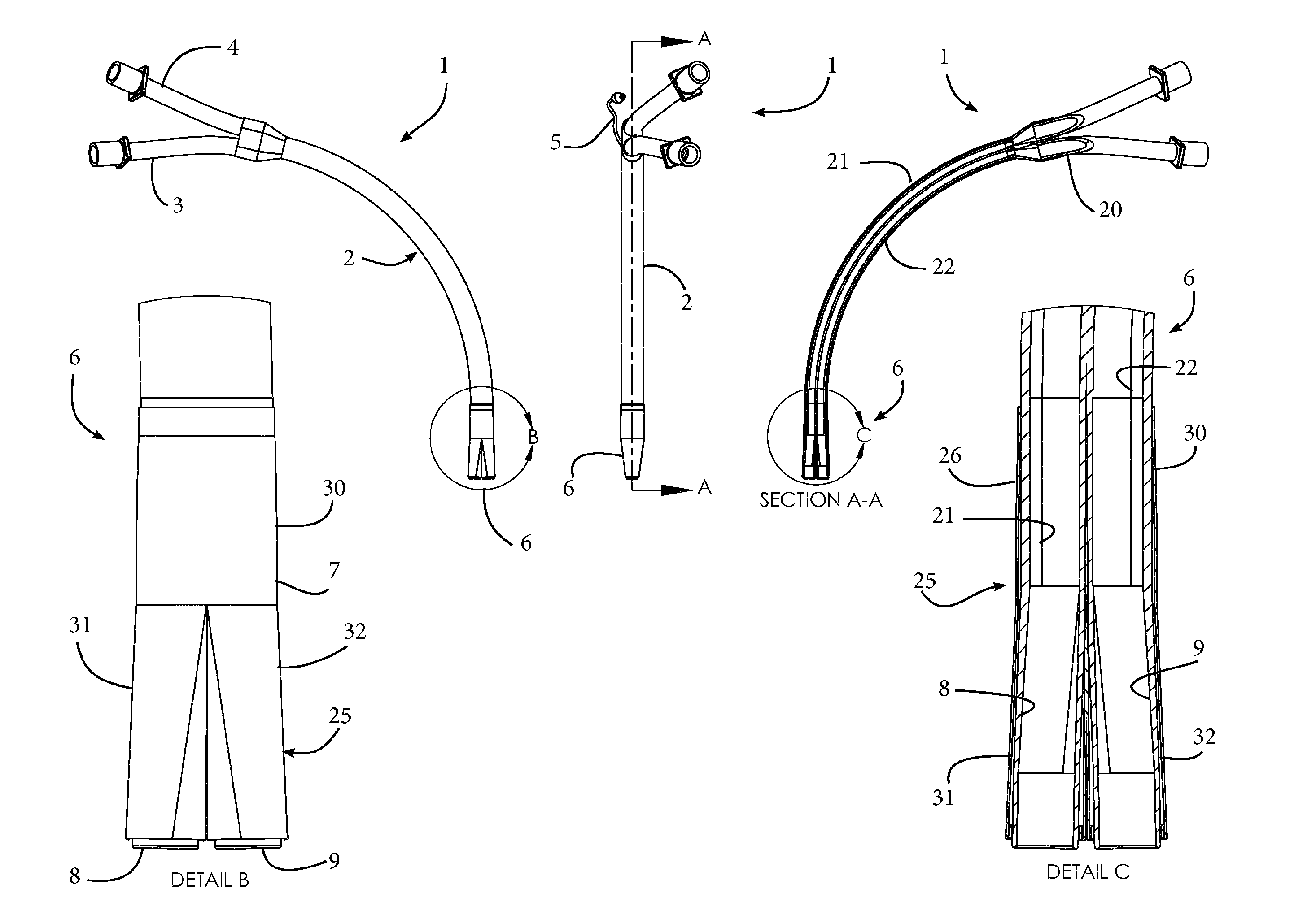
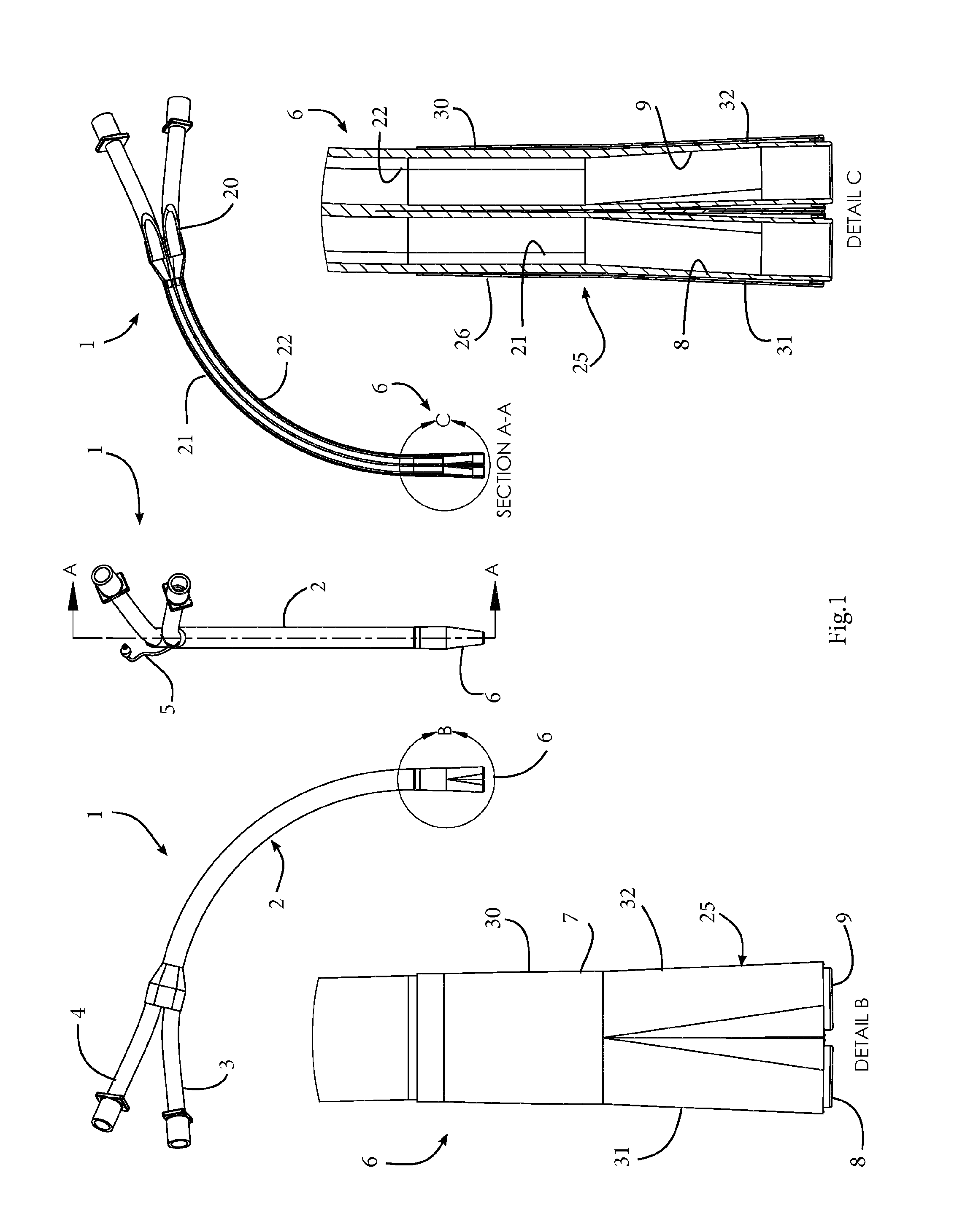
[0029]FIG. 1 is a set of views of a ventilation device of the invention, including a front view, a side view, a cross-sectional view along the lines A-A, an enlarged view B of the distal end of the device, and a cross-sectional view C through the distal end, and

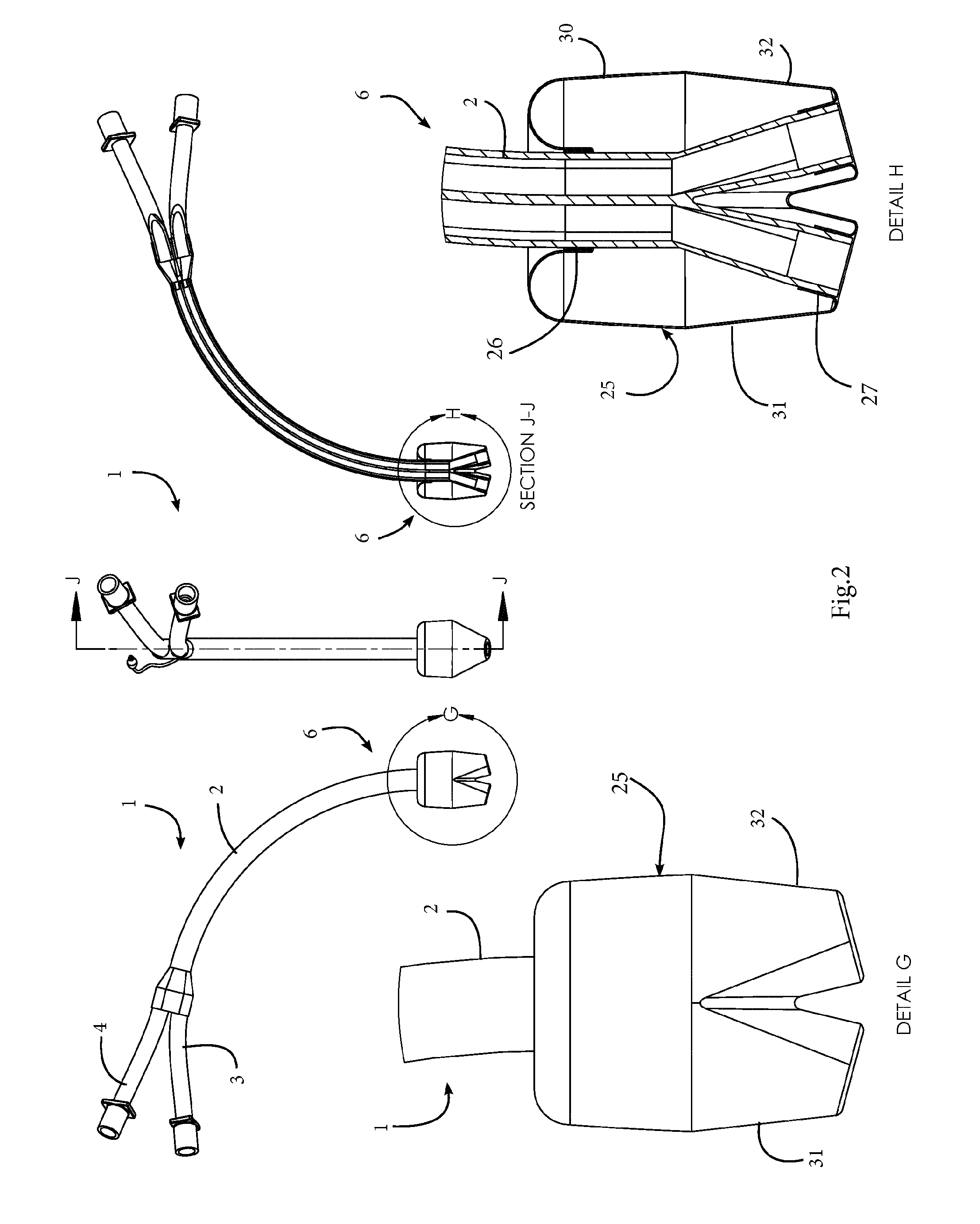
[0030]FIG. 2 is a set of corresponding views showing the device with the balloon inflated;

[0031]FIG. 3 is a set of similar views of a ventilation device of another embodiment, in which a distal tip has a link element between the distal portions,

[0032]FIG. 4 is a set of similar views in use showing this device being deployed by a surgeon as it is pushed towards the carina,

[0033]FIG. 5 shows the device on the carina when the link element has opened and

[0034]FIG. 6 shows the device when fully deployed with...


PUM


Abstract

A lung ventilation device has a stem to fit in a trachea, having at least two ventilation passageways communicating with distal passageways configured to fit in the bronchi at the carina. There is a positioning balloon to engage the walls at the carina when inflated. The positioning balloon has a proximal annular portion surrounding a distal end of the stem, and a plurality of annular distal portions, each surrounding a distal passageway end. The distal balloon portions are extensions of the proximal balloon portion. There may be a frangible link between the distal passageways, to break to separate the distal passageways in situ for bronchi entry as the positioning balloon is inflated. There may be stylets extending along the stem and arranged to provide stiffness to the distal passageways during device advancement in the trachea.

Description

FIELD OF THE INVENTION[0001]The invention relates to ventilation of the lungs.[0002]Ventilation of the lung is the process whereby gas enters and leaves the lung to allow exchange of oxygen and carbon dioxide between the alveoli and the blood. Normally this process is mechanically controlled by the action of the diaphragm. When the diaphragm contracts it descends and decreases intrathoracic pressure in the chest cavity, causing air to be pulled into the lungs through the trachea and bronchi.[0003]When a patient is under general anaesthesia disruption can occur to normal breathing. A mechanical ventilator is used to ensure continuous breathing by controlled flow of gas into a patient's airways. The ventilator may be in complete control of the patient's breathing or may only be assisting, depending on the desired settings of the anaesthetist.[0004]Gas is delivered from the ventilator using a tube which is placed directly into the patient's trachea / bronchus, depending on the surgical r...

Claims


Application Information

Patent Timeline
Patent Type & Authority Applications(United States)
IPC IPC(8): A61M16/04A61M5/00
CPCA61M16/0404A61M16/0445A61M5/007A61M16/0477A61M16/0459A61M16/0418A61M16/04A61M16/0434A61M16/0486
Inventor DALY, CHARLESBRENNEN, CIARANO'BRIEN, DECLANMURRAY, MYLESO'DRISCOLL, OLIVE
Owner CORK INST OF TECH
Why Eureka
Try Eureka