Method for manufacturing a fluid ejection device and fluid ejection device

Active Publication Date: 2014-10-23
STMICROELECTRONICS INT NV
View PDF2 Cites 57 Cited by
  • Summary
  • Abstract
  • Description
  • Claims
  • Application Information

AI Technical Summary

Benefits of technology

[0006]One or more embodiments of the present disclosure provide a method for m

Problems solved by technology

Known manufacturing methods envisage coupling via gluing or bonding of a large number of pre-machined wafers;

Method used


Image

  • Method for manufacturing a fluid ejection device and fluid ejection device
  • Method for manufacturing a fluid ejection device and fluid ejection device
  • Method for manufacturing a fluid ejection device and fluid ejection device

Examples


Embodiment Construction

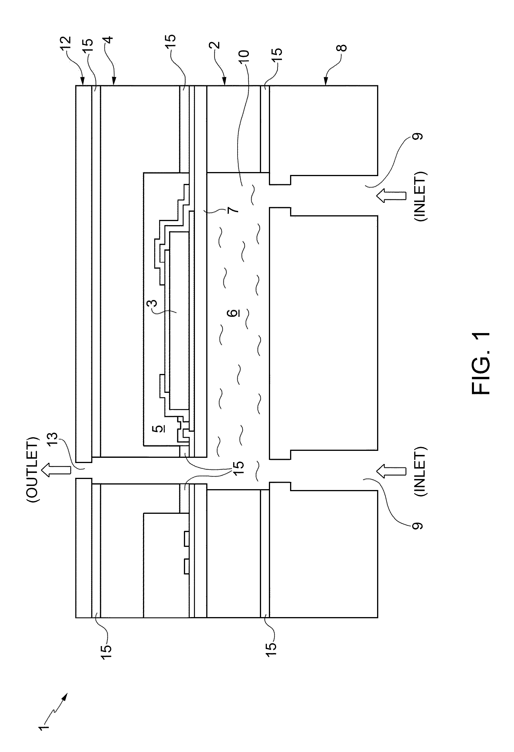
[0012]Fluid ejection devices based upon piezoelectric technology can be produced by bonding or gluing together a plurality of wafers machined previously using micromachining technologies typically used for manufacturing MEMS (microelectromechanical systems) devices. In particular, FIG. 1 shows a liquid-ejection device 1 that does not form part of the present disclosure. With reference to FIG. 1, a first wafer 2 is machined so as to form thereon one or more piezoelectric actuators 3, designed to be controlled for generating a deflection of a membrane 7, which extends partially suspended over one or more chambers 10 that are designed to define respective reservoirs for containing fluid 6 to be expelled during use. A second wafer 4 is machined so as to form one or more chambers 5 for containing the piezoelectric actuators 3 such as to insulate, in use, the piezoelectric actuators 3 from the fluid 6 to be expelled; a third wafer 8 is machined to form one or more inlet holes 9 of the flu...


PUM

PropertyMeasurementUnit
Electrical conductoraaaaaaaaaa
Areaaaaaaaaaaa
Distanceaaaaaaaaaa

Abstract

A method for manufacturing a fluid ejection device, comprising the steps of: providing a first semiconductor body having a membrane layer and a piezoelectric actuator which extends over the membrane layer; forming a cavity underneath the membrane layer to form a suspended membrane; providing a second semiconductor body; making, in the second semiconductor body, an inlet through hole configured to form a supply channel of the fluid ejection device; providing a third semiconductor body; forming a recess in the third semiconductor body; forming an outlet channel through the third semiconductor body to form an ejection nozzle of the fluid ejection device; coupling the first semiconductor body with the third semiconductor body and the first semiconductor body with the second semiconductor body in such a way that the piezoelectric actuator is completely housed in the first recess, and the second recess forms an internal chamber of the fluid ejection device.

Description

BACKGROUND[0001]1. Technical Field[0002]The present disclosure relates to a method for manufacturing a fluid ejection device and to a fluid ejection device. In particular, the present disclosure regards a process for manufacturing a head for fluid emission based upon piezoelectric technology, and to a head for fluid emission based on piezoelectric technology.[0003]2. Description of the Related Art[0004]Multiple types of fluid ejection devices are known in the prior art, in particular inkjet heads for printing applications (known as printheads). Heads of this sort, with appropriate modifications, may moreover be used for emission of fluids other than ink, for example, for applications in the biological or biomedical fields, for local application of biological material (e.g., DNA) during manufacture of sensors for biological analyses.[0005]Known manufacturing methods envisage coupling via gluing or bonding of a large number of pre-machined wafers; said method is costly and typically r...

Claims


Application Information

Patent Timeline
IPC IPC(8): B41J2/045
CPCB41J2/045B41J2/14233B41J2/161B41J2/1623B41J2002/1437B41J2/1628B41J2/1631Y10T29/49401
Inventor CATTANEO, MAUROCAMPEDELLI, ROBERTOVARISCO, IGOR
Owner STMICROELECTRONICS INT NV
Why Eureka
Try Eureka