Piezoelectrically actuated microvalve

a micro-valve and piezoelectric technology, applied in the direction of piezoelectric/electrostrictive devices, microstructural devices, microstructural technology, etc., can solve the problem of long piezoelectric ceramics

Inactive Publication Date: 2000-11-07
FRAUNHOFER GESELLSCHAFT ZUR FOERDERUNG DER ANGEWANDTEN FORSCHUNG EV
View PDF12 Cites 88 Cited by
  • Summary
  • Abstract
  • Description
  • Claims
  • Application Information

AI Technical Summary

Benefits of technology

The present invention is so conceived that a flow opening is provided within the valve seat which is implemented as a diaphragm portion of increased thickness, whereby the non-pressure-compensated area enclosed by the valve seat can be reduced and the force applied by the piezoactuator can be converted into an increased deflection and, consequently, into a higher flow rate through the valve.
By means of the microvalve according to the present invention, the construction size of piezoelectrically operated valves can substantially be reduced on the basis of a mechanical translation between a tappet and a piezoelectric actuator, said mechanical translation being provided by the suspension device of the tappet. By means of the lever translation, a comparatively small lateral shrinkage, i.e. a change in the dimensions of the piezoelectric ceramic in the longitudinal direction, is converted into a comparatively high vertical deflection of the valve tappet over the valve seat, i.e. a high deflection at right angles to the longitudinal dimensions of the piezoelectric ceramic. This permits large opening widths of the valve to be realized on a small area. In contrast to the hitherto known embodiments, the valves which will be described hereinbelow can, moreover, be mounted making use of a full-wafer connection technique which is generally used in the field of semiconductor technology. This means that a large number of identical components can be produced side by side ceramic. This permits large opening widths of the valve to be realized on a small area. In contrast to the hitherto known embodiments, the valves which will be described hereinbelow can, moreover, be mounted making use of a full-wafer connection technique which is generally used in the field of semiconductor technology. This means that a large number of identical components can be produced side by side on a substrate at the same time. The individual valves are then produced by dicing at the end of the manufacturing process. The use of this so-called batch process will increase the reproducability of the component specifications. By means of this kind of production it is possible to save costs, since the structures can be produced simultaneously, and to simplify production because the function can already be tested in the composite wafer structure.
The construction size of piezoelectrically operated microvalves having a structural design according to the present invention can be reduced drastically in comparison with known microvalves, the flow rate remaining, however, the same. This permits a higher packing density, e.g. in the case of so-called valve islands, so that e.g. pneumatically controlled machines can be reduced in size or actually be realized. Especially the use of microvalves in the field of motor vehicles is closely coupled with the construction size and the resultant weight of the microvalves. In addition, higher flow rates can be achieved when the hitherto used construction size is maintained. It follows that faster switching times, e.g. of working pistons, can be achieved. Due to the reduced construction size required for a given flow rate, the costs for the casing will be reduced as well.

Problems solved by technology

The microvalves described in the above publication are disadvantageous insofar as, for obtaining the deflection of the valve tappet over the valve seat which is necessary for a high flow rate, a very long piezoelectric ceramic is required, said valve tappet being also referred to as valve flap.

Method used


Image

  • Piezoelectrically actuated microvalve
  • Piezoelectrically actuated microvalve
  • Piezoelectrically actuated microvalve

Examples


first embodiment

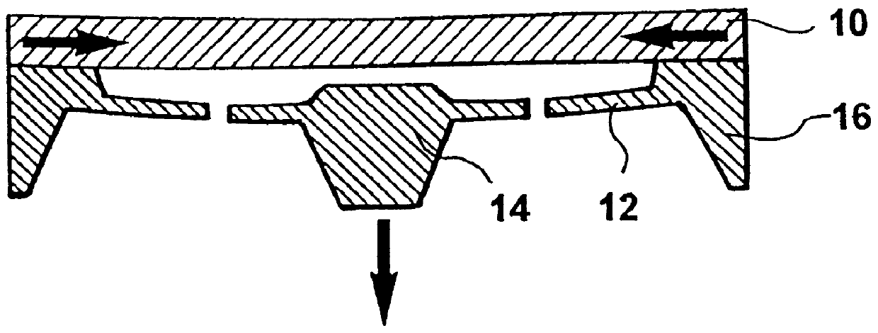
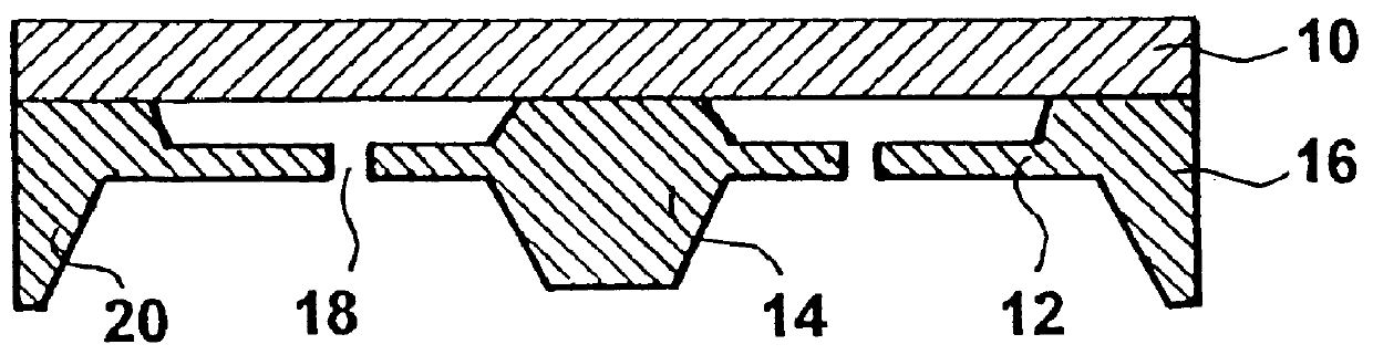
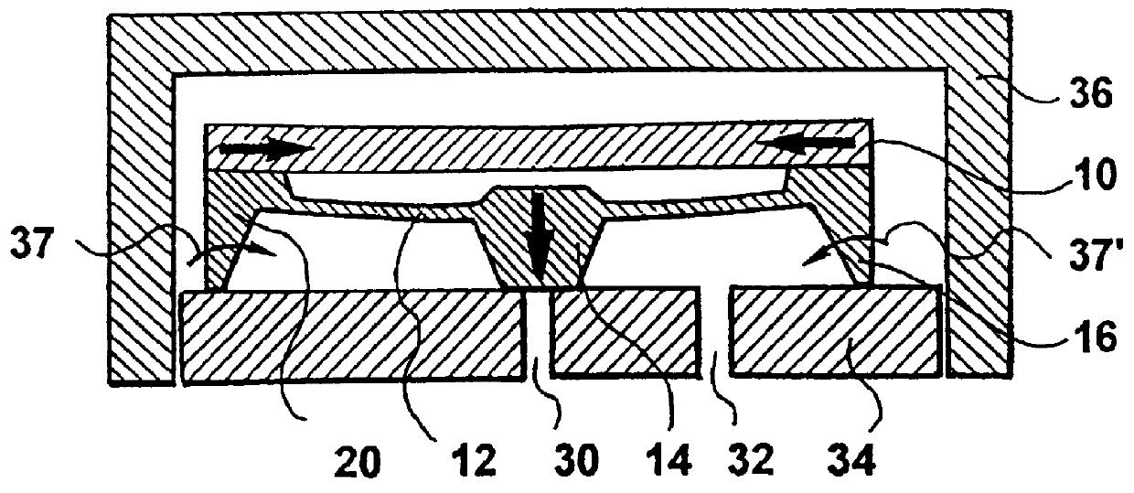
In FIGS. 2A and 2B, a microvalve is shown. The valve in question is a 2 / 2-NO (=normally open) microvalve, which is provided with two paths, i.e. two passage openings, and two switching states, the microvalve being open in the deactivated state. In the embodiment of the microvalve shown in FIGS. 2A and 2B, the valve openings 30 and 32 are provided in a base plate 34 consisting e.g. of ceramics. In addition, the base plate 34 can also be used for electric contacting. The valve openings 30 and 32 have fluid connections (not shown) attached thereto, e.g. a consumer connection and a pressure connection.

The base plate 34 has secured thereto a microstructured tappet chip 16 along its border, i.e. along its peripheral projection 20, in such a way that the tappet 14 is freely movable in the middle of the micromechanically structured chip 16, said tappet chip 16 corresponding in this embodiment to the chip shown in FIG. 1A and 1B. The micromechanically structured chip 16 has additionally atta...

second embodiment

FIG. 3 shows a microvalve. This embodiment is a 2 / 2-NC (=normally closed) valve, which is provided with two paths and two switching states and which is closed in the deactivated state. In the embodiment shown in FIG. 3, a micromechanically structured tappet chip 38 is again attached to a piezoelectric ceramic 40. The tappet chip 38 is again provided with a tappet 42 attached via an elastic suspension 44 to a part 46 of the tappet chip 38 which is connected to the piezoelectric ceramic 40 along the periphery of the tappet chip. In this case, the tappet chip is mounted on the piezoelectric ceramic 40 in such a way that the tappet 42 has already applied thereto a certain amount of mechanical prestress due to the mounting process and rests on the valve seat, whereby said valve seat is closed.

The embodiment shown in FIG. 3 again comprises a base plate 48, which consists e.g. of ceramics and which has two valve openings 50 and 52, and a casing cover 54. In this embodiment also the piezoel...

third embodiment

a microvalve is shown in FIG. 4. In the embodiment shown in FIG. 4, the base plate 48 with passage openings 50, 52 and the piezoelectric ceramic 40 with passage openings 56 and 58 have the same structural design as in the case of the embodiment which has been described making reference to FIG. 3. The piezoelectric ceramic has again arranged thereon a micromechanically structured tappet chip 60. The elastic suspensions by means of which the tappet 62 is secured to the part of the tappet chip 60 fastened to the piezoelectric ceramic 40 are provided with fluid passages which are shown as openings 64, by way of example.

The micromechanically structured tappet chip 60 is again provided with a peripheral projection 66 having arranged thereon a further valve seat 68 in the third embodiment according to the present invention. The valve seat 68 is provided with a passage opening 70. The passage opening 70 is in fluid communication with a passage opening 72 of a casing cover 74 encapsulating t...


PUM


Abstract

PCT No. PCT / EP97 / 06498 Sec. 371 Date May 20, 1999 Sec. 102(e) Date May 20, 1999 PCT Filed Nov. 20, 1997 PCT Pub. No. WO98 / 23869 PCT Pub. Date Jun. 4, 1998A microvalve includes a micromechanically structured chip defining a valve seat with a flow opening therethrough, an elastic suspension device and an edge region. A valve plate is defined by a piezoelectric actuator and is connected to the edge region of the micromechanically structured chip. The longitudinal dimension of the piezoelectric actuator are able to be changed by the application of an electric voltage. A decrease in the longitudinal dimension of the piezoelectric actuator caused by the application of an electric voltage is mechanically converted into a movement of the valve plate relative to the valve seat essentially at a right angle to the longitudinal direction. The connection of the piezoelectric actuator with the edge region of the micromechanically structured chip and the suspension device causes the conversion. Thus, the valve plate will open or close the flow opening in the valve seat.

Description

1. Field of the InventionThe present invention relates to micromechanically produced valves and especially to piezoelectrically operated microvalves.2. Description of Prior ArtMicrovalves can generally be used in the fields of pneumatics and fluidics for controlling the flow of gases and liquids, i.e. fluid flows. Such a valve can either have the function of a pilot valve or it can directly be used for controlling a volume flow or a pressure in a working piston or the like.Piezoelectrically operated microvalves which are known at present and which are based on the inverse piezoelectric effect comprise a large piezoelectric ceramic which is fixed at one end in most cases and by means of which the fluid flow is controlled directly. Such a piezoelectrically operated silicon microvalve is described in R. Ro.beta.berg, B. Schmidt, S. Buttgenbach: "Micro Liquid Dosing System", Microsystem Technologies 2 (1995), pages 11 to 16, Springer-Verlag 1995. In such microvalves, either the piezoele...

Claims


Application Information

Patent Timeline
Patent Type & Authority Patents(United States)
IPC IPC(8): B81B3/00F15C3/04F15C5/00F15C3/00F16K31/00H01L41/09F16K31/02F16K99/00
CPCF15C3/04F15C5/00F16K31/004F16K31/005F16K99/0005F16K99/0009F16K99/0048F16K99/0001F16K2099/009F16K2099/0074Y10T137/2213
Inventor KLUGE, STEFAN
Owner FRAUNHOFER GESELLSCHAFT ZUR FOERDERUNG DER ANGEWANDTEN FORSCHUNG EV
Why Eureka
Try Eureka