The inventive arrangement provides a durable and wear-resistant flexibly movable connection of the flap relative to the main airfoil body of the rotor blade. Moreover, this flexible connection or junction of the flap to the main airfoil body provided by the flexible junction element is also capable of withstanding the high loads that arise, and allows the necessary flap movements at high frequencies without suffering substantial wear. For this reason, the inspection and maintenance intervals can be considerably extended in comparison to the prior art.
The flexible junction element is preferably made of a
fiber-reinforced synthetic or plastic
composite material, in which the fibers may be glass fibers, for example. The fibers in the
composite material achieve an especially high strength with a low weight, i.e. a high strength to weight ratio. The use of glass fibers in this context makes it possible to achieve a particularly high elasticity or insensitivity to strain as well as a high durability and high fatigue strength of the flexible junction element. In order to achieve the flexible bending at a desired location, the junction element preferably includes a flexible bending portion having a reduced thickness as compared to the other portions of the junction element adjoining the flexible bending portion. With this arrangement, the flexible bending will preferentially occur about a virtual axis in the thinner flexible portion.
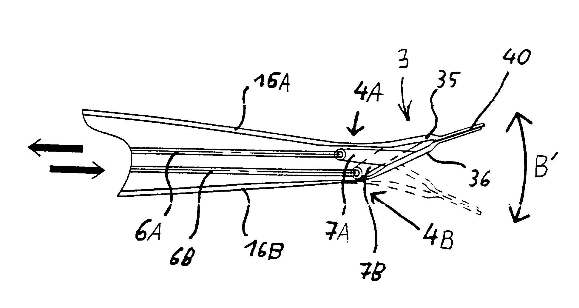
The main airfoil body of the rotor blade is preferably constructed with top and bottom skins or walls over a skeleton of spars and ribbing or over a cellular or foam core or the like or even enclosing a
hollow core therein. With such a construction, a flexible junction element preferably connects the top
skin of the main airfoil body with the upper part of the flap, and / or a flexible junction element connects the bottom
skin of the main airfoil body with a lower part of the flap. In this manner, a particularly good aerodynamic
surface contour of the overall rotor blade is achieved.
With such an arrangement, it is possible to securely and directly connect the upper part of the flap to the top
skin of the main airfoil body, and simultaneously securely connect the lower part of the flap to the bottom skin of the main airfoil body, by means of respective flexible junction elements. When the flap is deflected, this arrangement avoids the formation of a gap between the flap and the main airfoil body, so that a smooth, closed aerodynamic transition is formed by the respective flexible junction elements. The occurrence of wearing abrasion along the
sliding contact surface is also avoided.
It is preferred that the flexible junction element and the respective parts of the rotor blade and / or of the flap adjoining the junction element are embodied in an integral or one-piece manner, and most advantageously along the entire width of the junction element. The junction element may thus be an integral component essentially consisting of a
fiber-reinforced
composite material. Especially, the junction element may be arranged in the
axis of symmetry of the flap, whereby the possibility of a kinking or over-bending of the junction element can be avoided. Preferably, the flap is moved or actuated by means of at least one lever arm, which connects the upper part and / or the lower part of the flap to the
actuator via a push rod or pull rod for transmitting the actuating forces. In this manner, it is possible to move the flap or the respective upper and lower flap parts by means of pulling tension forces or pushing compression forces, which is advantageous for being able to use a piezoelectric
actuator. Each flap part can be actuated by a separate lever arm, whereby the total force needed for moving the flap is divided between two actuator linkages, whereby the wear and loads are reduced.
In a particular advantageous embodiment, the actuator linkage comprises a fiber joint between the rod and the lever arm, for transmitting the actuating force to the flap or respective flap part. The rod can be embodied as a simple pull rod or tension rod that is preferably fabricated of one or more fibers and especially glass fibers. This feature makes it possible to actuate the upward and downward deflection of the flap using only tension forces, whereby the occurrence of wear between the lever arm and the rod can be reduced or eliminated. Moreover, this embodiment achieves a high strength, a high durability, and a high fatigue strength of the overall linkage, combined with a small structural size as well as a low weight.

