Direct torque flow constant velocity joint having collet connection

a constant velocity, joint technology, applied in the direction of screw threaded joints, rod connections, couplings, etc., can solve the problems of reducing affecting the service life of the connection, so as to reduce the improve the service life, and reduce the effect of radial and axial clearan

Inactive Publication Date: 2011-08-16
GKN DRIVELINE NORTH AMERICA
View PDF11 Cites 10 Cited by
  • Summary
  • Abstract
  • Description
  • Claims
  • Application Information

AI Technical Summary

Benefits of technology

[0005]Accordingly, the present invention provides a direct torque flow constant velocity joint (DTF CVJ) having a collet connection. The DTF CVJ collet connector has a neck or extension axially extending from an inner joint part providing a female or indirect connection type directly to a shaft of a drive unit, such as a transmission, transfer case or axle, while reducing radial and axial clearance. The DTF CVJ collet connector allows for additional flexibility by providing for improved installation, inspection or service at the connection interface.

Problems solved by technology

However, axial and radial clearances of the joint at the connection interface may be compromised for a given torque transfer capability.
Moreover, this type of connection may be difficult to install, inspect or service.

Method used


Image

  • Direct torque flow constant velocity joint having collet connection
  • Direct torque flow constant velocity joint having collet connection
  • Direct torque flow constant velocity joint having collet connection

Examples


first embodiment

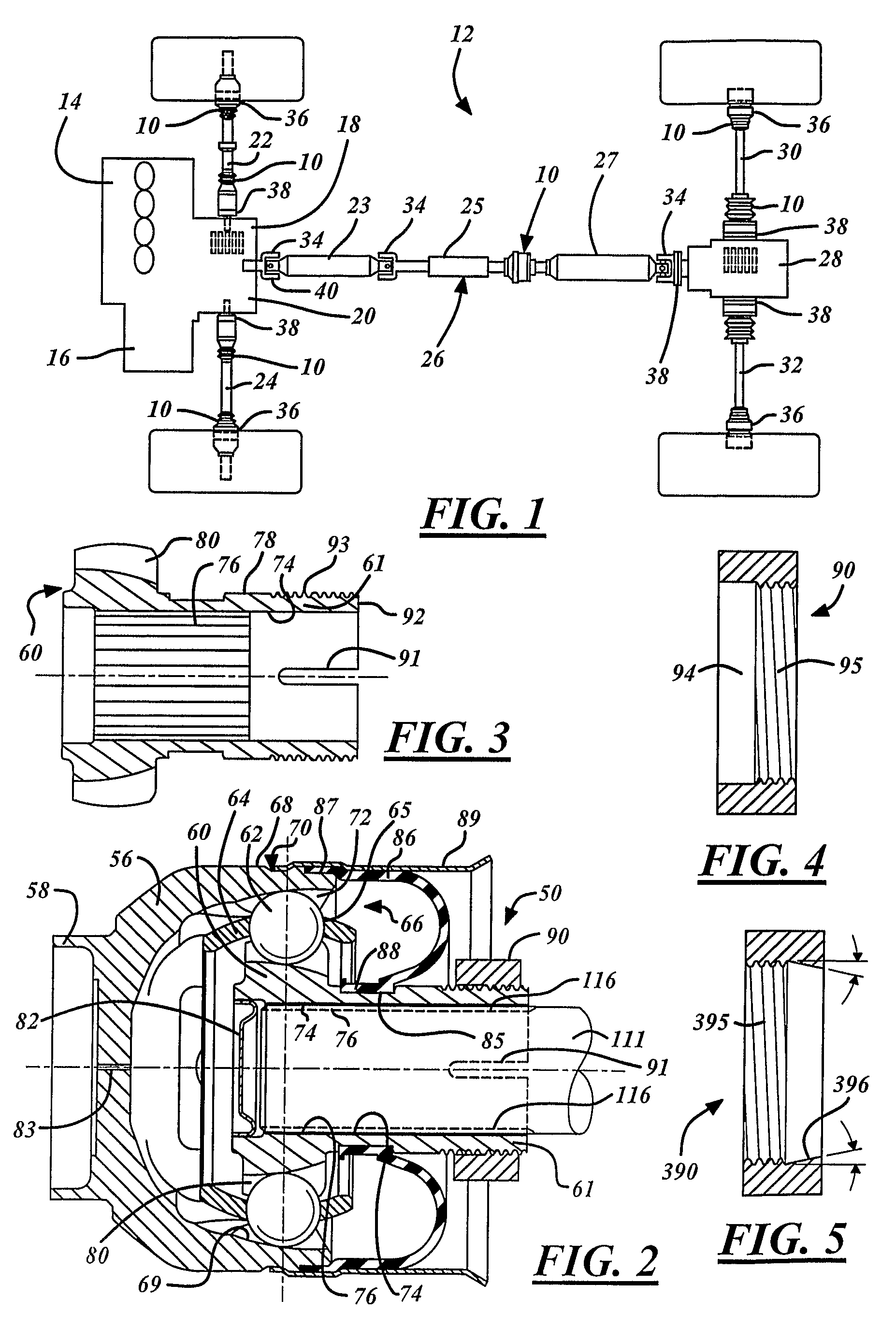
[0032]FIG. 5 shows a second compression nut 390 that may be optionally used to advantage according to the invention. Compressive force may be applied to the collet extension 61 of the inner joint part 60 by a second compression nut 390. The second compression nut 390 includes threads 395 for engaging a collet threaded portion 93 of an inner joint part 60 and a compression taper 396 for compressing the collet extension 61 of the inner joint part 60. While, the compression taper 396 is shown as conical, the compression taper 396 may have any shape capable of providing compressive force upon an inner joint part 60 as would be recognized by a person of skill in the art. Accordingly, the compression nut 390 may compressively engage the inner joint part 60 thereby allowing axial retention of the DTF CVJ collet connector 50 to a shaft journal 111 of a drive unit when connected thereto.

[0033]Optionally, the inner joint part 60 may include a collet taper (not shown) on an outer surface 78 of...

second embodiment

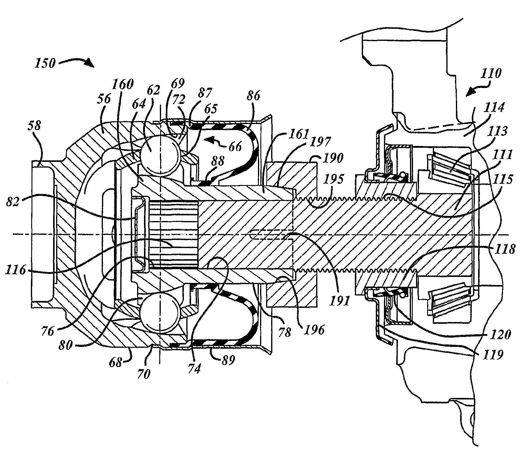
[0034]FIG. 6 shows an inventive direct torque flow constant velocity joint collet connector 150. The inner joint part 160 includes a collet extension 161 and one or more relief slots 191. The collet extension 161 axially extends the inner joint part 160 in the general direction of a differential 110 generally extending beyond the ball tracks 80. The collet extension 161 includes a collet taper 197 on an outer surface 78 and extends from a front portion 92 of the inner joint part 160. The one or more relief slots 191 extend into the collet extension from the front portion 92 between the outer surface 78 and an inner-bore 74 of the inner joint part 160. The one or more relief slots 191 allow the inner bore 74 along the relief slot 191 to be decreased when compressive forces are applied to the outer surface 78 of the collet extension 161 thereby clamping and axially retaining the DTF CVJ collet connector 150 to a shaft journal 111. It is recognized that any number of slots 191 may be u...

third embodiment

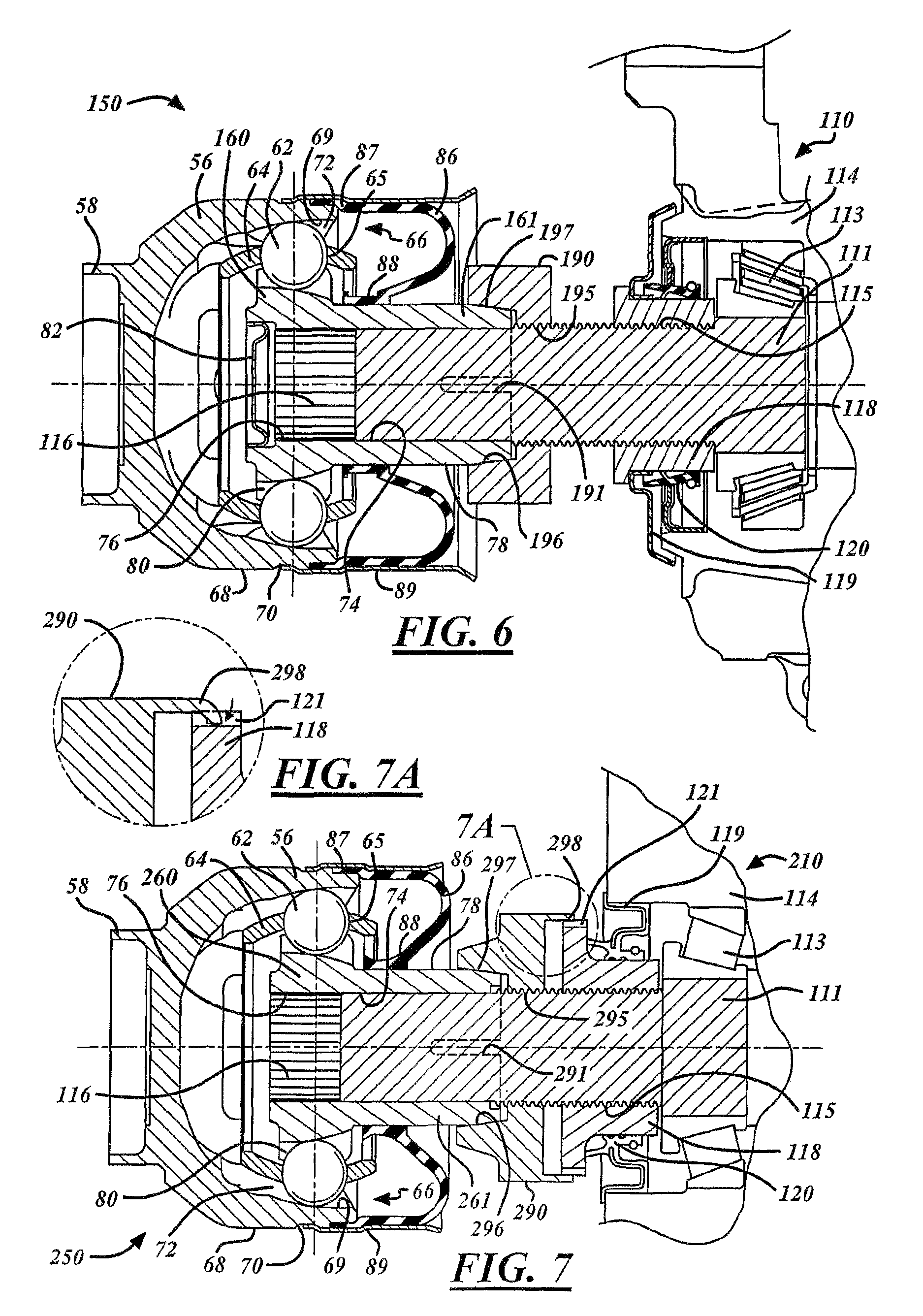
[0036]FIG. 7 shows an inventive direct torque flow constant velocity joint collet connector 250. Inner joint part 260 includes a collet extension 261 and one or more relief slots 291. The collet extension 261 axially extends the inner joint part 260 in the general direction of a differential 110 generally extending beyond a plurality of ball track 80. The collet extension 261 includes a collet taper 297 on an outer surface 78 and extends from a front portion 92 of the inner joint part 260. The one or more relief slots 291 extend into the collet extension from the front portion 92 between the outer surface 78 and an inner bore 74 of the inner joint part 260. The one or more relief slots 291 allow the inner bore 74 along the relief slot 291 to be decreased when compressive forces are applied to the outer surface 78 of the collet extension 261 thereby clamping and axially retaining the DTF CVJ collet connector 250 to a shaft journal 111. It is recognized that any number of slots 291 ma...


PUM


Abstract

A direct torque flow constant velocity joint collet connector includes an outer joint part having outer ball tracks, an inner joint part having inner ball tracks, a cage and a plurality of balls. The inner joint part is articulately secured in a rotationally fast way to the outer joint part with the plurality of balls held in the cage. The inner joint part includes a front portion, an inner bore, a collet extension and at least one slot. The collet extension extends from the inner ball tracks to the front portion of the inner joint part. The slot extends into the collet extension from the front portion between an outer surface and the inner bore of the inner joint part, wherein the collet extension of the inner joint part is compressible for selective attachment to a journal shaft of a supplied drive unit.

Description

TECHNICAL FIELD[0001]The present invention relates generally to motor vehicle shaft joints, and more particularly concerns a direct torque flow constant velocity joint having a colleted connection.BACKGROUND ART[0002]Constant velocity joints connecting shafts to drive units are common components in automotive vehicles. The drive unit typically has an output shaft or an input shaft for receiving the joint. Typically, the drive unit is an axle, transfer case, transmission, power take-off unit or other torque device, all of which are common components in automotive vehicles. Typically, one or more joints are assembled to the shaft to form a propeller or drive shaft assembly. It is the propeller shaft assembly, which is connected, for instance, at one end to an output shaft of a transmission and, at the other end, to an input shaft of a differential. The shaft is solid or tubular with ends adapted to attach the shaft to an inner race of the joint thereby allowing an outer race connectio...

Claims


Application Information

Patent Timeline
Patent Type & Authority Patents(United States)
IPC IPC(8): F16D3/223
CPCF16D1/087F16D1/09F16D3/223Y10T403/67Y10S464/906F16D2001/0955Y10T403/7058F16D2003/22323
Inventor HAHN, STEVEN C.WORMSBAECHER, HANS
Owner GKN DRIVELINE NORTH AMERICA
Why Eureka
Try Eureka