
Remote tower monitoring system

Pending Publication Date: 2020-01-23
SMART TOWER SYST LLC
View PDF0 Cites 4 Cited by
  • Summary
  • Abstract
  • Description
  • Claims
  • Application Information

AI Technical Summary

Benefits of technology

The tower monitoring system can track changes in a tower over time to diagnose problems, such as corrosion, loose parts, or excessive loading. The system can also identify under-utilized structures that could bring in more revenue, optimize inspection intervals to reduce service trips, and help address damaged towers more efficiently. Overall, the system can make towers safer, reliable, and cost-effective.

Problems solved by technology

Thus, the tower may be affected by various external phenomena, such as natural disasters, environmental factors, physical contact, potentially destructive wind oscillations leading to fatigue failures and normal wear and tear.
Thus, as a tower interacts with the various external phenomena, the tower's efficacy may be compromised.
In the former case, engaging a specialist may be costly, ineffective, and a non-robust solution.
Further, certain towers may be in areas that are geographically remote, and thus, not very easy to travel to.
Further, in the latter case, if towers are repaired after a problem is detected, considerable downtime may be experienced.
Because the tower is compromised (and in some cases beyond repair), the system associated with the tower may be rendered inoperable until the tower is either repaired or replaced.
Conventional techniques for structural health monitoring for detecting deformations are directed to rotational or tilting detection using tilt sensors that are not reliable on flexible structures, such as a tower, as a result of acceleration during displacement corrupting the sensor's measurements.
Serious structural health issues may be missed without detecting tower displacements as well as rotations, and thus, these problems may be left unaddressed in detecting, monitoring, and repairing issues affecting tower implementations.
Thus, the conventional techniques for addressing tower related problems associated with structural integrity and performance are lacking for at least the above-stated reasons.

Method used


Image

  • Remote tower monitoring system
  • Remote tower monitoring system
  • Remote tower monitoring system

Examples


Embodiment Construction

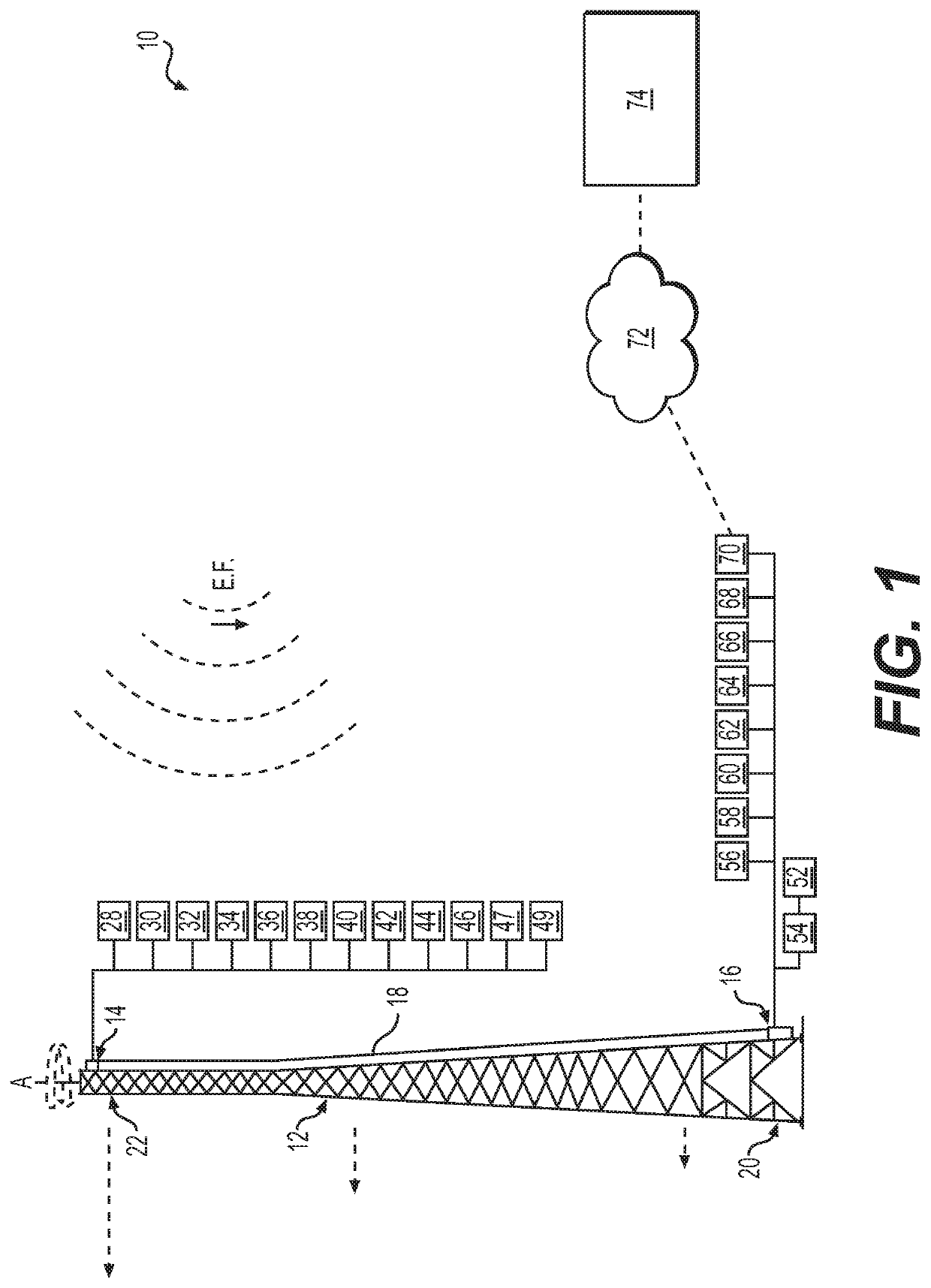
[0021]Referring to the Figures, wherein like numerals indicate corresponding parts throughout the several views, one aspect of the present invention is related to a tower monitoring system 10 that is capable of monitoring and analyzing the structural health of the tower 12 in real-time and / or near real-time and providing historical data for trend analysis or other evaluations. As discussed in further detail below, the system 10 is uniquely capable of measuring the magnitude and direction of lateral displacements and twist and sway rotations, permanent deformations, destructive oscillations and is capable of performing a modal analysis to evaluate the dynamic responses of the tower to external forces. Such external forces include wind, ice and earthquake forces as well as other, less regular forces like impacts, tower climbers, construction activity, wildlife, and others.

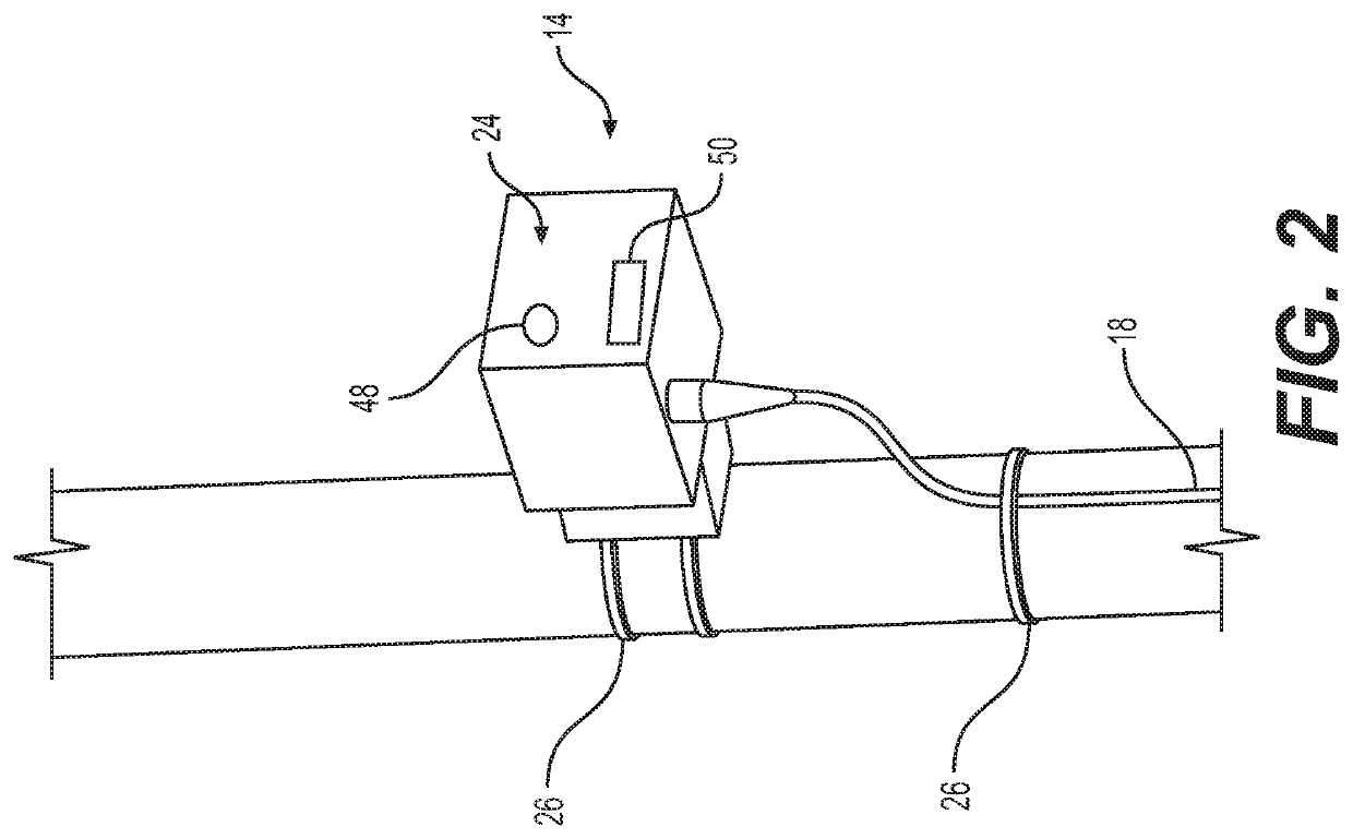
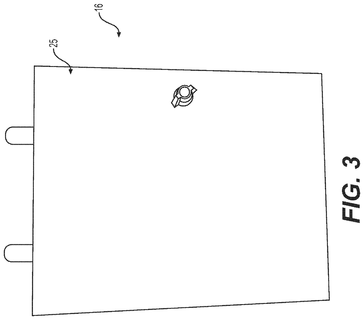
[0022]Referring initially to FIGS. 1 through 3, aspects of the tower monitoring system 10 are shown in accordance ...


PUM


Abstract

A tower monitoring system for monitoring a remote tower for structural evaluation and analysis. The tower monitoring system includes a sensor unit that takes tower data readings that include displacement readings. The sensor unit provides the tower data readings to a ground control unit near the tower. A remote server is in communication with the ground control unit and includes a secondary source of data, such as historical data of the tower, current data or historic data from nearby towers, and nearby weather and geological data. The monitoring system implements a modal analysis to determine contributions to the displacement readings and alarms an operator if the modal readings indicate structural stress beyond a predetermined threshold. Data is saved and can be used in a trend analysis to review any changes in the tower displacement readings over a period of time.

Description

CROSS-REFERENCE TO RELATED APPLICATION[0001]This Patent Application claims the benefit of and priority to U.S. Provisional Patent Application Ser. No. 62 / 699,951 filed on Jul. 18, 2018, and titled “Remote Tower Monitoring System,” the entire disclosure of which is hereby incorporated by reference.BACKGROUND OF THE INVENTION1. Field of the Invention[0002]The present invention is related generally to systems for monitoring towers and more particularly systems to provide data for structural evaluation and analysis.2. Related Art[0003]Towers are employed for a plurality of applications. For example, towers are employed to transmit resources such as energy, oil, water, etc. or information from a first location to another. The information being propagated from a first point to a second point may be network related, energy related, communications related, or the like. In another context, a tower may be situated to collect information about a location, such as weather or other environmental...

Claims


Application Information

Patent Timeline
IPC IPC(8): G01M5/00G08B21/18
CPCG01M5/0066G01M5/0025G08B21/182G01M5/0058
Inventor BRINKER, DAVID G.
Owner SMART TOWER SYST LLC
Learn More