Adjustable downlighter

a downlighter and adjustable technology, applied in the direction of light fastenings, transportation and packaging, lighting and heating equipment, etc., can solve the problems of hazard and violation of regulations, inflexible installation, and the inability to rotate the light beam up to the horizontal plan

Active Publication Date: 2014-10-23
THOMSON JAMES WAUGH
View PDF7 Cites 5 Cited by
  • Summary
  • Abstract
  • Description
  • Claims
  • Application Information

AI Technical Summary

Problems solved by technology

These are limited and inflexible in installation and use, and risk shining distracting and disturbing light sideways, which poses a hazard and breach of regulations.
Therefore the light beam cannot be rotated up to the horizontal plane to shine to the front or the rear for example, since this could conflict with the lighting regulations.
but a limited vertical spread angle

Method used


Image

  • Adjustable downlighter
  • Adjustable downlighter
  • Adjustable downlighter

Examples


Embodiment Construction

[0067]Some particular embodiments a down light of the invention will now be described by way of example only with reference to accompanying diagrammatic and schematic drawings in which:

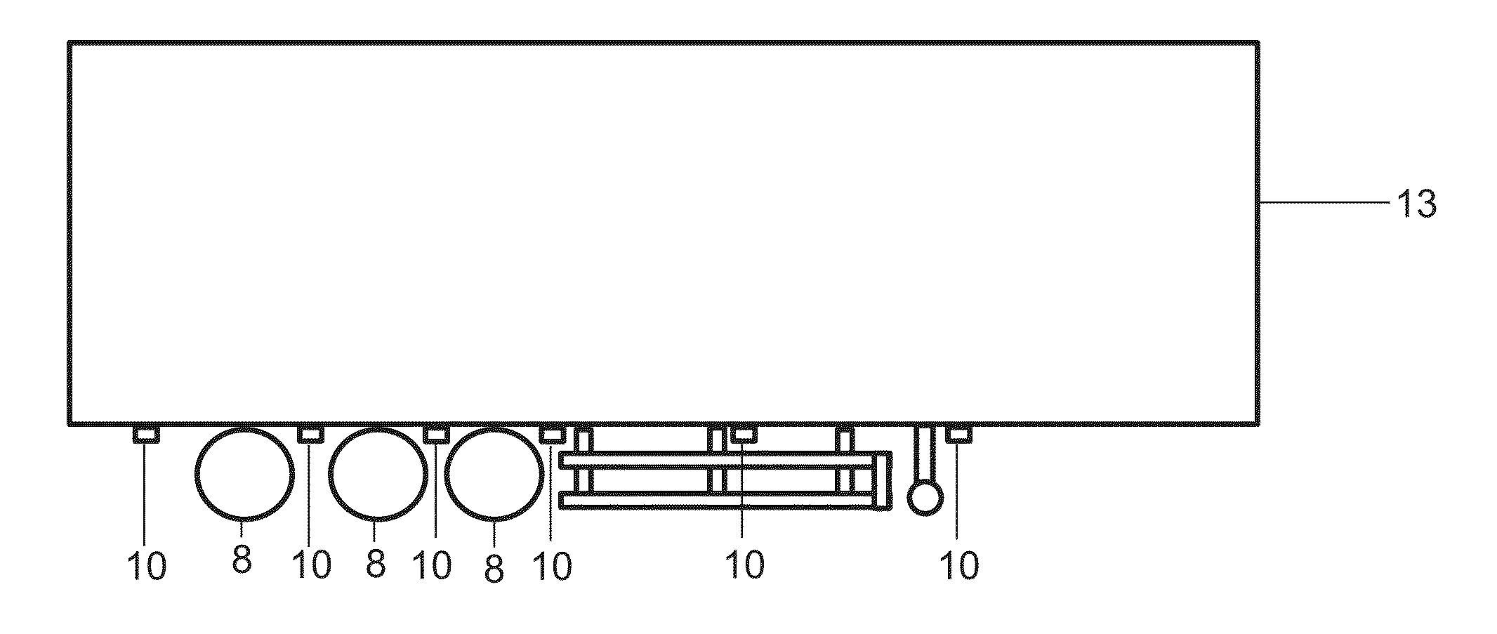
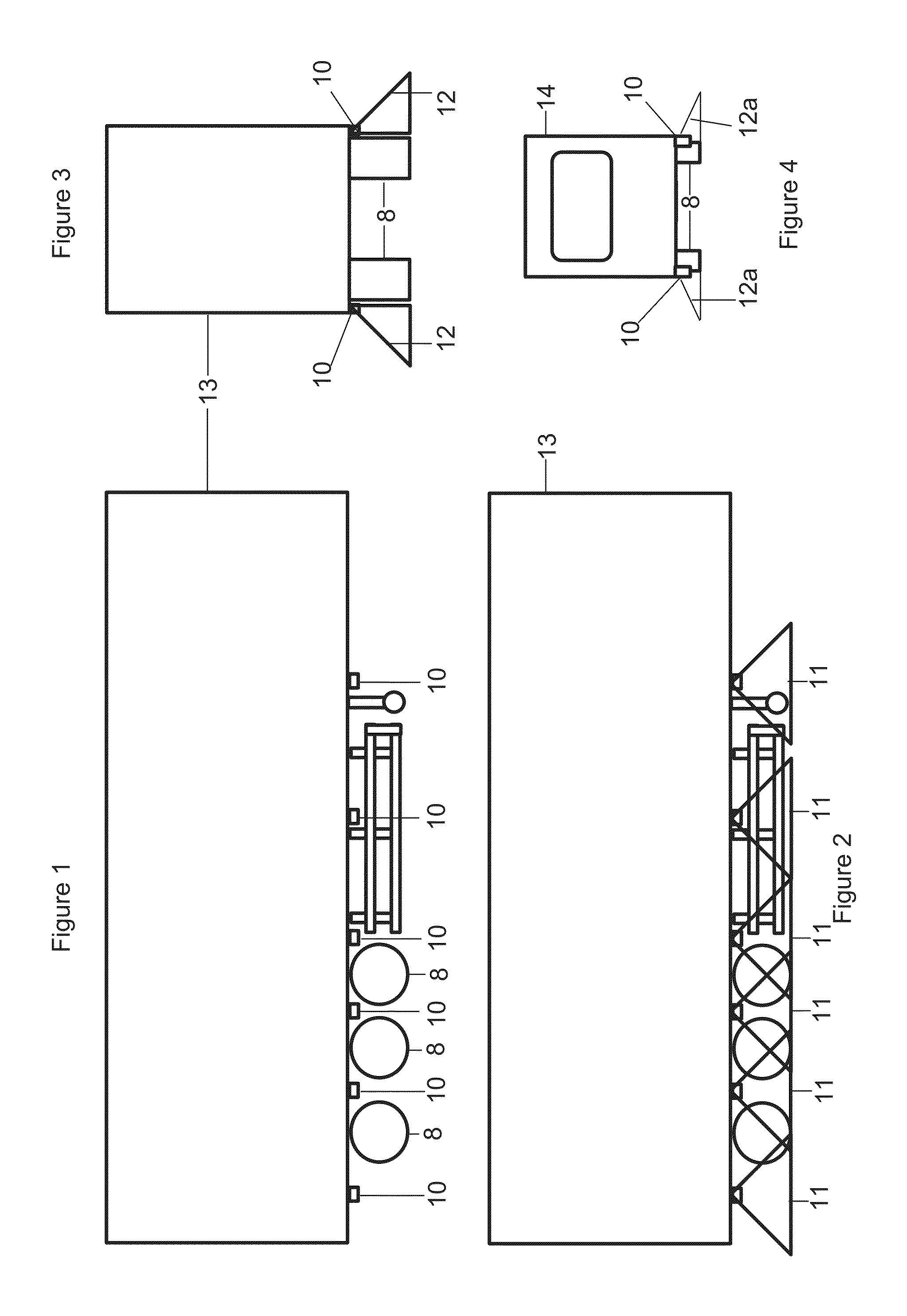
[0068]FIG. 1 shows the fitment of a downlight 10 along the side edge but within the confines of a semi-trailer 13.

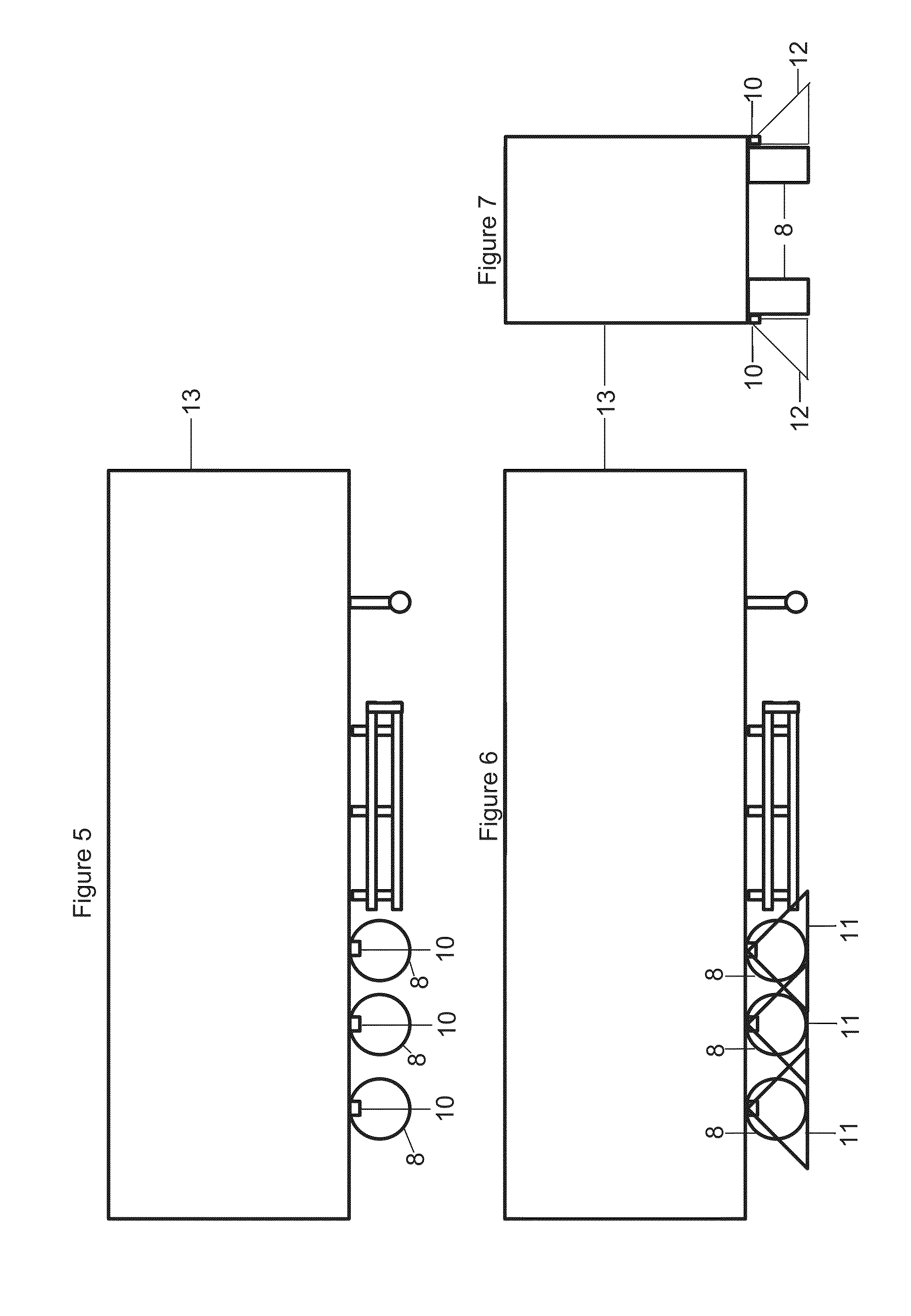
[0069]FIG. 2 shows the horizontal light spread 11 from the downlight 10 when fitted high up on the chassis of a semi-trailer (13).

[0070]FIG. 3 shows from the rear, the vertical angle of the light spread 12 from the downlight 10, covering the area adjacent to the sides, when fitted high up on the chassis of a semi-trailer (13) but within the confines of the vehicle / trailer.

[0071]FIG. 4 shows from the rear, the shallower vertical angle of the light outward spread 12a from the downlight 10 by tilting the light assembly 20 to a different greater angle, offering a shallower angle of light spread 12a, when fitted lower to the ground on a caravan 14 but within the confines of the caravan.

[0072]FI...


PUM


Abstract

A vehicle or trailer side marker and/or downlight (10) includes a casing or housing (1) and adjustable mounting (4,5),
an internal reflector an internal baffle or shield, a light source, a lens or diffuser cover to allow adjustment of beam orientation, direction or angular spread to determine ground spread and beam upper margin limits so as not to dazzle others.

Description

[0001]This invention relates to vehicle lighting and is particularly but not exclusively concerned with visual marking and delineation of a freight or goods road vehicle or trailer, for the benefit of a vehicle driver and drivers of other vehicles, pedestrians or remote bystanders. Driver needs are not the same as those of others and so may not be best served by the same light format. Marking to a vehicle sides is one consideration. For convenience the term vehicle is used herein to embrace a self-propelled truck or towed or towable trailer, or indeed any other movable body to which a downlight may be fitted.BACKGROUND TO THE INVENTION[0002]When driving a motor vehicle and / or trailer combination it can be a problem for the driver to see along the side perimeter and the safe clearance area surrounding the sides of the vehicle. Front mounted headlights give illumination to the front and in some respects a wider forward field of vision beyond that of the vehicle width, at least when lo...

Claims


Application Information

Patent Timeline
Patent Type & Authority Applications(United States)
IPC IPC(8): B60Q1/32
CPCB60Q1/32B60Q1/484B60Q1/247B60Q1/48
Inventor THOMSON, JAMES WAUGH
Owner THOMSON JAMES WAUGH
Why Eureka
Try Eureka