High density enclosure for optical modules

a technology of optical modules and enclosures, applied in the field of high density enclosures for optical modules, can solve the problems of limited density using lgx enclosures, or any existing proprietary enclosures that are similar, and the design of optical component enclosures using the lgx standard and related proprietary equipment enclosures is limited, so as to achieve high density and performance. high, the effect of improving density

Active Publication Date: 2014-10-23
M2 OPTICS
View PDF8 Cites 17 Cited by
  • Summary
  • Abstract
  • Description
  • Claims
  • Application Information

AI Technical Summary

Problems solved by technology

As a starting point, it is recognized that the packaging density using the LGX enclosures, or any of the existing proprietary enclosures that are similar, is limited by the number of modular containers that can be packed closely together along the front panel of a rack mounted enclosure with their integral optical connectors facing outward.
Since the maximum depth dimension of a typical modular container is only a fraction of the depth permitted by an equipment rack, there is normally a considerable amount of empty space behind the modular containers that is not utilized.
Basically, the optical component density using the LGX standard and related proprietary equipment enclosures designs is limited to a 1-dimensional array of cassettes that must be so positioned to provide access to their surface mounted connectors.
Any remaining space behind these cassettes in the equipment rack can not be utilized.

Method used


Image

  • High density enclosure for optical modules
  • High density enclosure for optical modules
  • High density enclosure for optical modules

Examples


Embodiment Construction

[0020]With reference to the attached drawings, embodiments of the present invention will be described below.

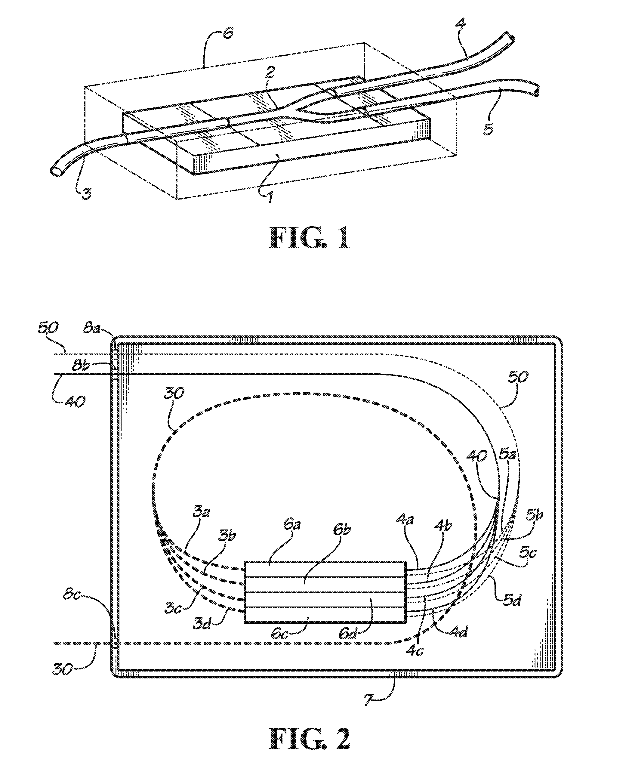
[0021]FIG. 1 shows the basic construction of a typical optical tap made using planar lightwave circuit (PLC) technology. The optical circuit is formed on substrate 1 that is a polished wafer of pure fused silica or a wafer of semiconductor silicon covered on its top side with the deposition of a relatively thick layer of pure silicon dioxide (SiO2) that is approximately 20 microns thick. On the very top of substrate 1 there is a second deposited layer of doped silica glass that is approximately 7 microns thick that has been patterned using techniques similar to semiconductor processing. The refractive index of this deposited layer is approximately 0.3% greater than that of pure fused silica. In the case of the optical tap, after processing, the remaining doped layer of silica glass has been reduced to a relatively simple “Y” shape 2 as shown in FIG. 1. This serves as a planar ...


PUM


Abstract

Rack mountable equipment enclosures have been developed that contain a multiplicity of fiber optical component such as optical taps, arrayed waveguide gratings (AWGs), optical splitters, and optical switches at a greater component density than has been previously achieved. For example, 192 fiber optical taps can be contained in a standard 19 inch wide equipment enclosure that is only 1 Rack Unit (1.75 inches) high. This high component density is achieved by locating the optical components within a multiplicity of modular containers inside of the equipment enclosure. The components are connected to fiber optic pig-tails that extend beyond the modular containers. These pig-tails are terminated with multi-fiber connectors that are mounted on the front panel of the equipment enclosure. This strategy allows for efficient packing of the modular containers containing optical components in the full volume of the rack space that is available to the equipment enclosure.

Description

CROSS-REFERENCES TO RELATED APPLICATIONS[0001]This application claims the benefit of U.S. Provisional Patent Application Ser. No. 61 / 854,402 filed Apr. 22, 2013, the contents of which are hereby incorporated by reference herein.TECHNICAL FIELD AND INDUSTRIAL APPLICABILITY OF THE INVENTION[0002]The present invention relates to packaging of fiber optic components (including taps, splitters, arrayed waveguide gratings, and switches) with high packing densities in order to fit a large number of components into an enclosure that will occupy a minimum space in equipment racks that are used in support of various types of fiber optic communication systems.BACKGROUND OF INVENTION[0003]Terrestrial communications throughout the world has grown to rely heavily on optical fiber communications technology. And there is an increasing flow of signaling information that requires use of multiple optical fibers in communication links from one point to another. The various origination, termination, and ...

Claims


Application Information

Patent Timeline
Patent Type & Authority Applications(United States)
IPC IPC(8): G02B6/44
CPCG02B6/4439G02B6/4452G02B6/30G02B6/3825G02B6/3885G02B6/3897G02B6/444G02B6/4454G02B6/4455
Inventor MILLER, GARY EVANJOHNSTON, OTIS JAMESMILLER, KEVIN WILLIAM
Owner M2 OPTICS
Why Eureka
Try Eureka