
NAT sub-topology management server

a technology of topology management and sub-topology, applied in the field of communication network technology, can solve the problems of not having a data base or document for managing taking a lot of labor and time to do, and administrators often cannot accurately grasp the ip hosts in operation from the document or the data base, etc., to achieve the effect of quick and accurate grasping a list of ip hosts in operation

Inactive Publication Date: 2014-10-23
HITACHI LTD
View PDF4 Cites 9 Cited by
  • Summary
  • Abstract
  • Description
  • Claims
  • Application Information

AI Technical Summary

Benefits of technology

The patent text describes a way for a network administrator to quickly and accurately find a list of IP hosts that are actively connected to a network using NAT functions. This makes it easy for them to manage the network and identify potential security threats.

Problems solved by technology

However, there is no data base or no document for management of the IP hosts in operation.
Therefore, the administrator often cannot accurately grasp the IP hosts in operation from the document or the data base.
It is a problem in this case that the administrator has to go to the site of the DC to retrieve all devices physically connected to the network inside the DC, check the setting states of IP addresses of OSs as to all the devices and create a list of IP hosts based on the results of the checked setting states.
It takes lots of labor and time to do this work, causing the increase of an operating load.

Method used


Image

  • NAT sub-topology management server
  • NAT sub-topology management server
  • NAT sub-topology management server

Examples


embodiment 1

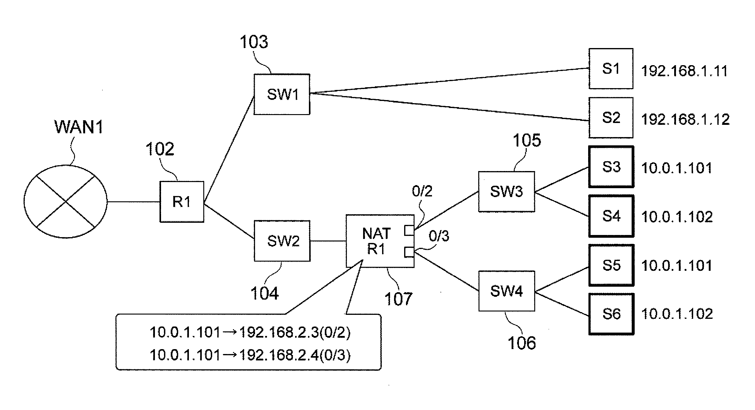
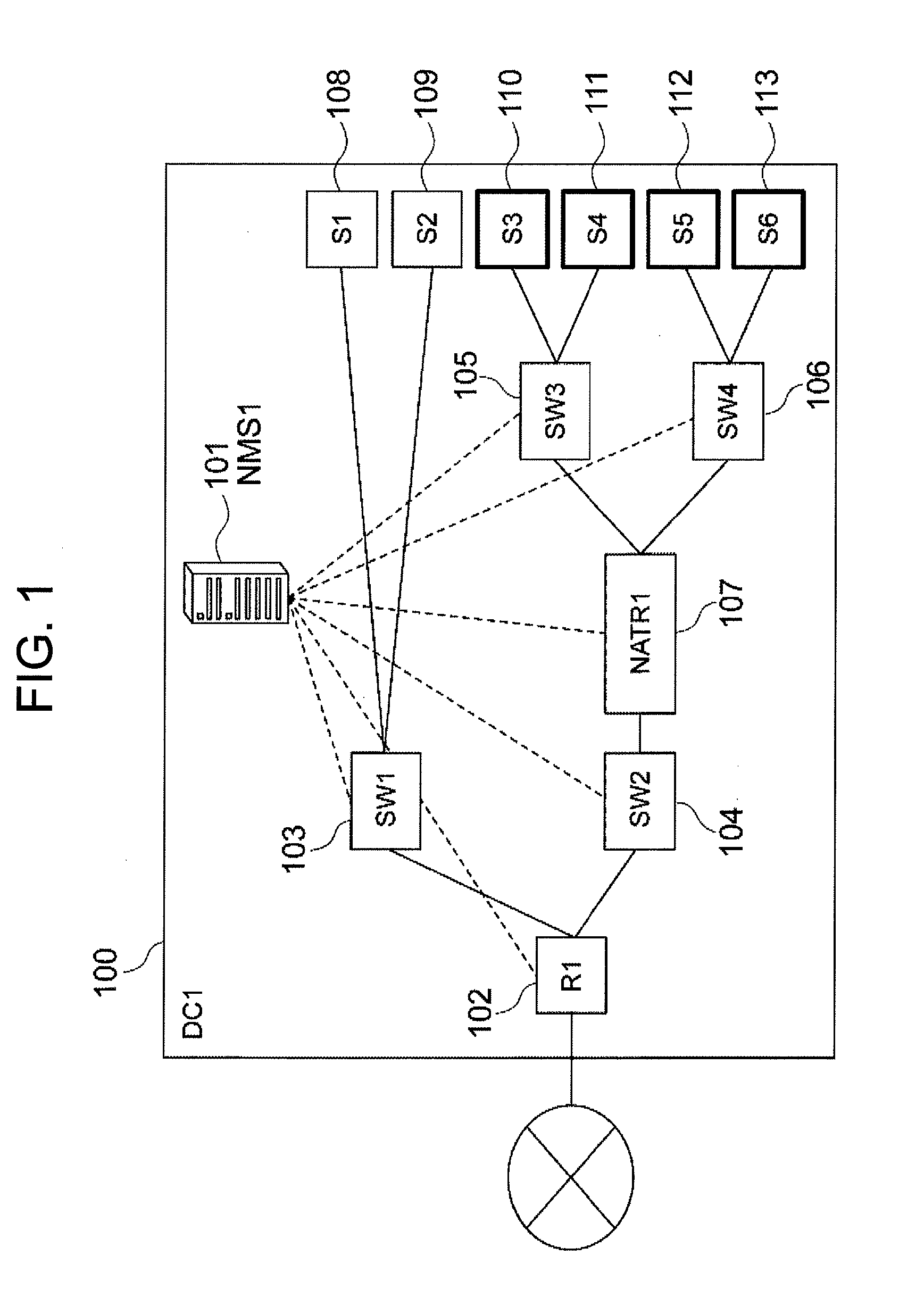
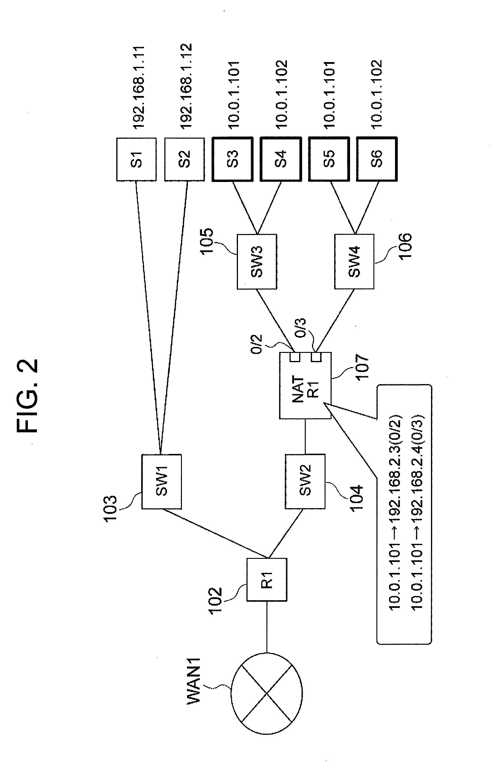
[0063]FIG. 1 shows a configuration example of a network system to be managed by a NAT sub-topology management server according to the invention. The NAT sub-topology management server NMS1 (101) according to the invention manages a network constituted by a router R1 (102), Ethernet switches SW1 to SW4 (103 to 106), a NAT-compatible router NATR1, and servers S1 to S6, which are disposed inside a data center DC1 (100). The network to be managed is connected from respective bases of clients of a data center service through a wide area network WAN1 of a wide area networking service provided by a carrier.

[0064]In this example, the router R1 (102) is connected to the wide area network WAN1. In addition, the router R1 (102) is connected to the switches SW1 (103) and SW2 (104). In addition, the SW2 (104) is connected to the NAT-compatible router NATR1. In addition, the NAT-compatible router NATR1 is connected to the switches SW3 (105) and SW4 (106). Further, each of the SW1 (103), the SW3 (...

embodiment 2

[0135]In a second embodiment of the invention, a network management server manages IP devices having IPv6 (Internet Protocol Version 6) addresses. The embodiment will be described below with reference to the drawings.

[0136]FIG. 24 shows a configuration example of a NAT sub-topology management server NMS2 (2401) according to the invention. The NAT sub-topology management server NMS2 includes a CPU, a memory, an I / O connecting an input / output device, a network adaptor connecting the NAT sub-topology management server NMS2 (2401) to an external network NW1, and an external memory device. In the NAT sub-topology management server NMS2 (2401), topology information 1 collected from switches, the aforementioned NAT setting information 2 collected from a NAT-compatible router, and an ARP table 3 collected from a router are provided on the memory. Likewise, NAT sub-topology information 4, NAT sub-topology information 5, an IP host information generator 6, IP host information 7, group informa...


PUM


Abstract

In a network where network address translation (NAT) has been introduced, a problem occurs in which, when an IP host operating in a network is automatically categorized with automatic IP host discovery using an ARP cache, a plurality of IP hosts with the same IP address are recognized as one IP host by NAT. To resolve this problem, a network management server specifies network sub-topology on the basis of topology information, public addresses translated by NAT, and IP host corresponding relationships.

Description

INCORPORATION BY REFERENCE[0001]The present application claims the priority of Japanese Patent Application No. 2011-185474 filed on Aug. 29, 2011, the contents of which are incorporated herein by reference.TECHNICAL FIELD[0002]The present invention relates to a communication network technology.BACKGROUND ART[0003]In a data center (DC), there often arises a situation in which an administrator wants to grasp IP hosts which are really in operation. However, there is no data base or no document for management of the IP hosts in operation. If any, the contents of the data base or the document do not match with the real state of the network. Therefore, the administrator often cannot accurately grasp the IP hosts in operation from the document or the data base.[0004]It is a problem in this case that the administrator has to go to the site of the DC to retrieve all devices physically connected to the network inside the DC, check the setting states of IP addresses of OSs as to all the device...

Claims


Application Information

Patent Timeline
Patent Type & Authority Applications(United States)
IPC IPC(8): H04L29/12H04L45/741
CPCH04L61/6068H04L61/2557H04L61/103H04L61/2514H04L41/122H04L41/12H04L2101/668
Inventor OKITA, HIDEKIYASUDANAKAYAMA, MARIKOHIMURA, YOSUKEYUMOTO, KAZUMA
Owner HITACHI LTD
Learn More