Flashing and Joiner for Window Installations

a technology of window installation and joiner, which is applied in the direction of snow traps, structural elements, building components, etc., can solve the problems of affecting the sealing effect of the window frame, the sill of the window frame should not be completely sealed, and the junction between the window frame and the cladding is often problemati

Inactive Publication Date: 2014-10-30
SMART REVEAL
View PDF38 Cites 11 Cited by
  • Summary
  • Abstract
  • Description
  • Claims
  • Application Information

AI Technical Summary

Benefits of technology

[0014]a first longitudinal wall extending from the window frame side of the support plate, and one or more longitudinal stiffening box sections continuous with said plate for imparting rigidity thereto, wherein two of the sections comprise sill and header flashings spaced apart at either end by the remaining two sections, which comprise jamb flashings; and
[0015]joiners connecting adjacent ends of said four sections, each joiner including one or more pairs of biscuit portions with each biscuit of a pair being dimensioned to be received into a box section of a respective flashing,

Problems solved by technology

Given the myriad of cladding types and building construction styles the junction between the window frame and the cladding is often problematic since it varies depending on the type of window frame and the type of cladding in each construction situation.
In addition to the above concern, whenever a window is installed into a building wall there is a possibility that the window frame could leak.
However, the sill of the window frame should not be completely sealed as drainage must be incorporated into the sill to allow for the discharge of moisture such as condensation which may build up around the window.
It would be desirable if a product were provided that would support the frame but at the same time encourage drainage of condensation to an outside of the frame and which would present an obstacle to ingress of condensation or other moisture into the building.

Method used


Image

  • Flashing and Joiner for Window Installations
  • Flashing and Joiner for Window Installations
  • Flashing and Joiner for Window Installations

Examples


Embodiment Construction

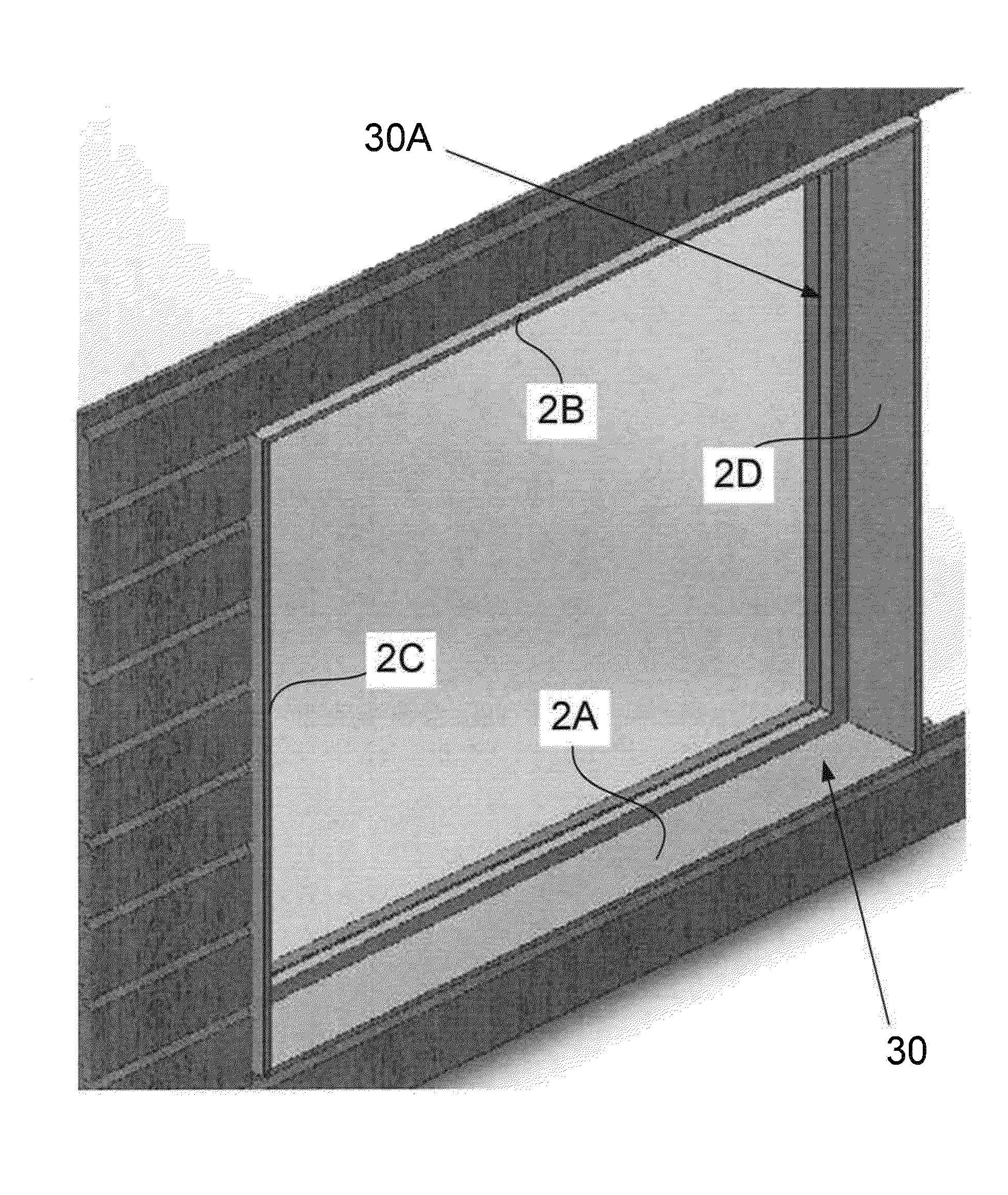
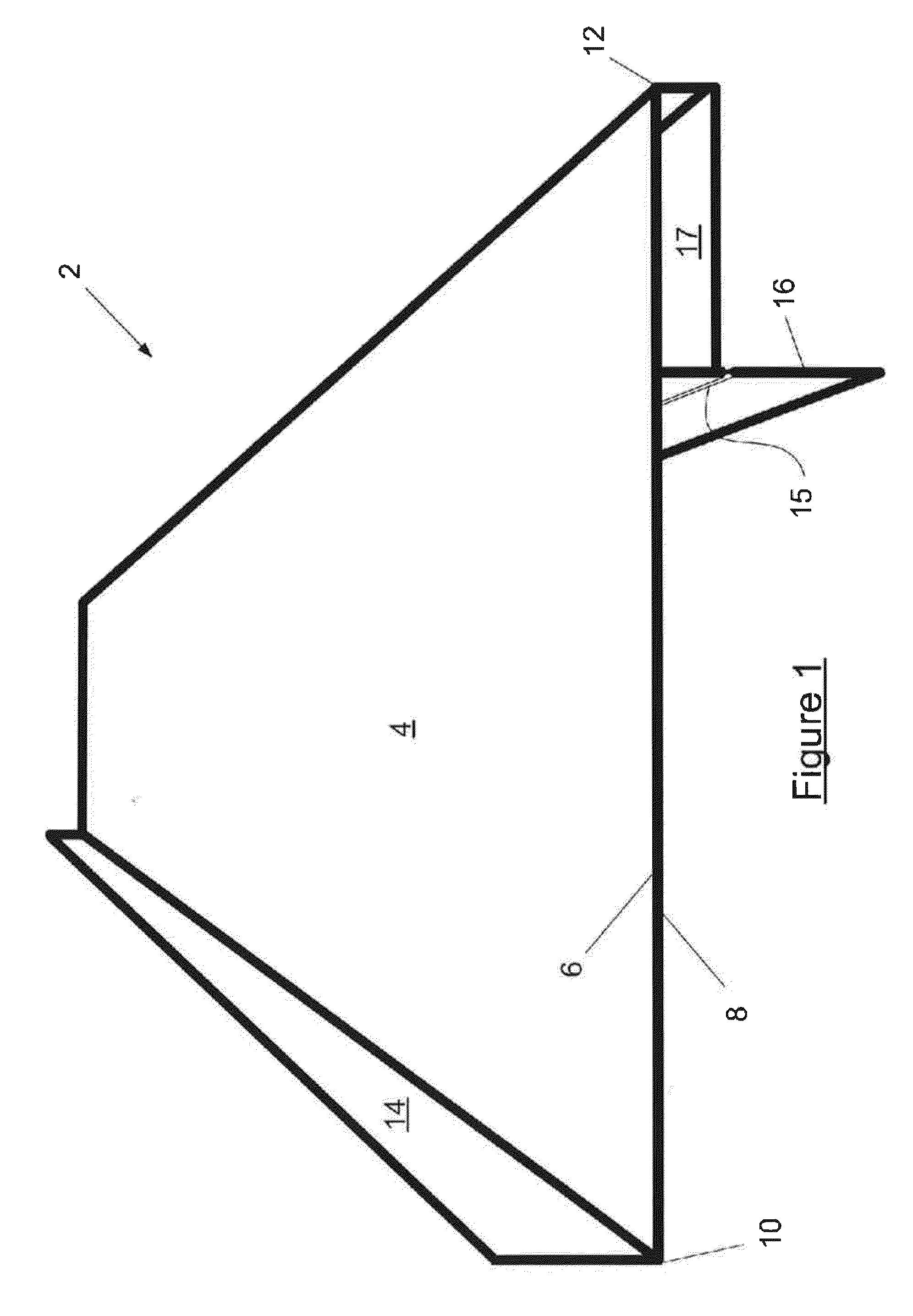
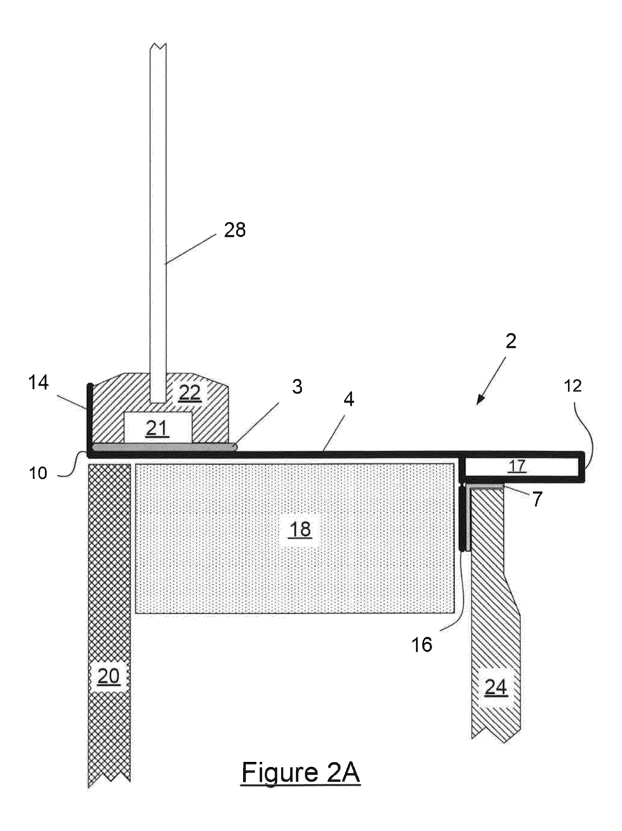
[0045]Referring now to FIG. 1, there is shown in single point perspective view, a length of a flashing 2 according to a preferred embodiment of the present invention. FIG. 2A is an end view of the flashing 2 in use installed in a wall of a building and supporting a window frame. FIG. 2B is a front plan view of the assembly depicted in FIG. 2A.

[0046]Flashing 2 is preferably formed as an aluminum extrusion, though other types of material, for example various plastics, may also be suitable.

[0047]The flashing comprises an elongate window frame support plate 4 which has a window frame support side 6 (identified in FIG. 1) and opposite thereto a building framework side 8. The flashing has an inner end 10, which in use is toward or inside the interior of the building in which it is installed, and an outer end 12, which locates proximate the exterior of the building in use.

[0048]Extending from the window frame side of the inner end there is a first longitudinal wall or “fin” or “upstand”14....


PUM


Abstract

A support frame for a window frame is provided to address the problem of unwanted entry of moisture, such as condensation, into a building in which the window frame is mounted. The support frame includes four sections of flashing. Each section of flashing has a window frame support plate that has a window frame side and building framework side. A first longitudinal wall extends from the window frame side of the support plate. One or more longitudinal stiffening box sections continuous with the plate are provided for imparting rigidity to the flashing. Two of the sections comprise sill and header flashings spaced apart at either end by the remaining two sections, which comprise jamb flashings. Joiners connect adjacent ends of the four sections.

Description

CROSS REFERENCE TO RELATED APPLICATION[0001]This application takes priority from and claims the benefit of Australian Patent Applications No. AU 2013901507 filed on Apr. 30, 2013 and No. AU 2013903516 filed on Sep. 12, 2013.TECHNICAL FIELD[0002]The present invention is directed to a flashing, and to a frame comprised of a number of lengths of the flashing, for use in the installation of building openings such as window frames.BACKGROUND[0003]Any references to methods, apparatus or documents of the prior art are not to be taken as constituting any evidence or admission that they formed, or form part of the common general knowledge.[0004]Many buildings are constructed about a timber or steel framework. The framework is typically covered with a membrane and cladding on its outer side. The cladding may be any of a number of different types. For example, it is known to use timber and also synthetic weatherboards, a single layer of brick or even rendered polystyrene foam.[0005]Window fram...

Claims


Application Information

Patent Timeline
Patent Type & Authority Applications(United States)
IPC IPC(8): E06B7/14E04B1/64E04B1/68
CPCE06B7/14E04B1/64E04B1/6803E06B1/02E06B1/342E06B1/68E06B1/702E06B3/9641E06B3/9616E06B3/9632E06B3/9647E06B3/9684
Inventor COSTA, DEAN
Owner SMART REVEAL
Why Eureka
Try Eureka