Active Device Substrate and Manufacturing Method Thereof

a technology of active devices and substrates, applied in the manufacture of final products, printed circuit aspects, basic electric elements, etc., can solve the problems of difficult to completely separate flexible substrates and glass plates, and damage to active devices

Active Publication Date: 2014-11-06
AU OPTRONICS CORP
View PDF0 Cites 11 Cited by
  • Summary
  • Abstract
  • Description
  • Claims
  • Application Information

AI Technical Summary

Benefits of technology

[0006]In the manufacturing process of the flexible active device substrate, it is convenient to fix a flexible substrate on a glass plate and then dispose active devices on the flexible substrate to form the flexible active device substrate. Afterwards, the flexible active device substrate is separated from the glass plate. However, when the attractive forces between the flexible substrate and the glass plate is too large, it is difficult to completely separate the flexible substrate and the glass plate so that the active devices may be damaged. Therefore, many in the industry are striving to improve the peeling manufacture of the flexible active device substrate.

Problems solved by technology

However, when the attractive forces between the flexible substrate and the glass plate is too large, it is difficult to completely separate the flexible substrate and the glass plate so that the active devices may be damaged.

Method used


Image

  • Active Device Substrate and Manufacturing Method Thereof
  • Active Device Substrate and Manufacturing Method Thereof
  • Active Device Substrate and Manufacturing Method Thereof

Examples


Embodiment Construction

[0027]In the following detailed description, for purposes of explanation, numerous specific details are set forth in order to provide a thorough understanding of the disclosed embodiments. It will be apparent, however, that one or more embodiments may be practiced without these specific details. In other instances, well-known structures and devices are schematically depicted in order to simplify the drawings.

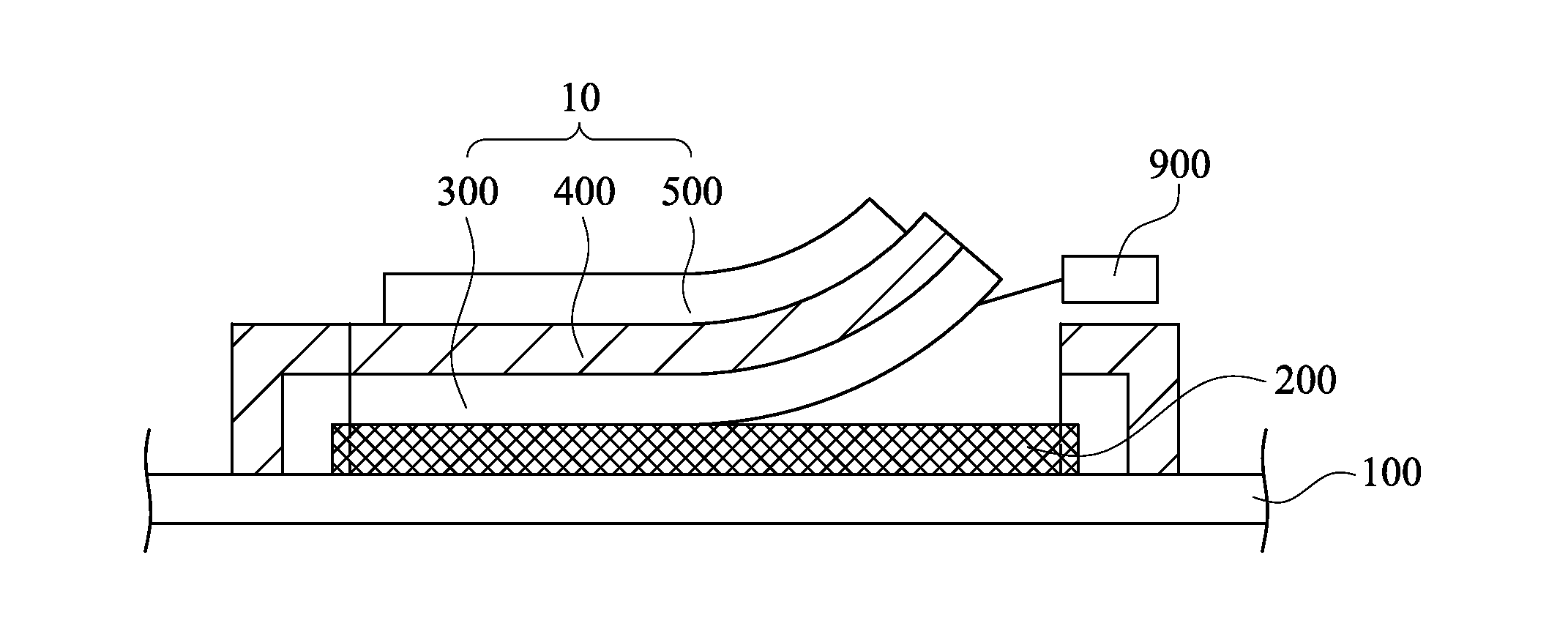
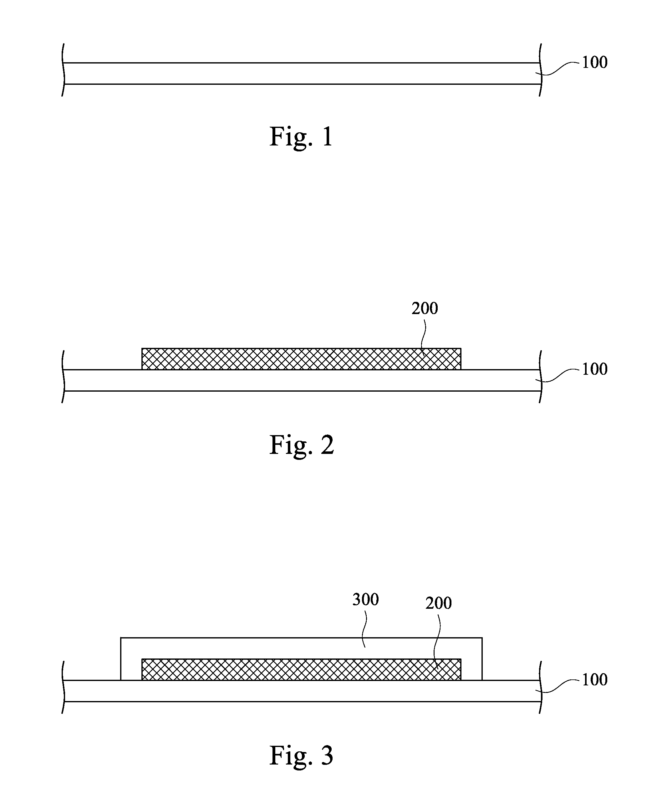
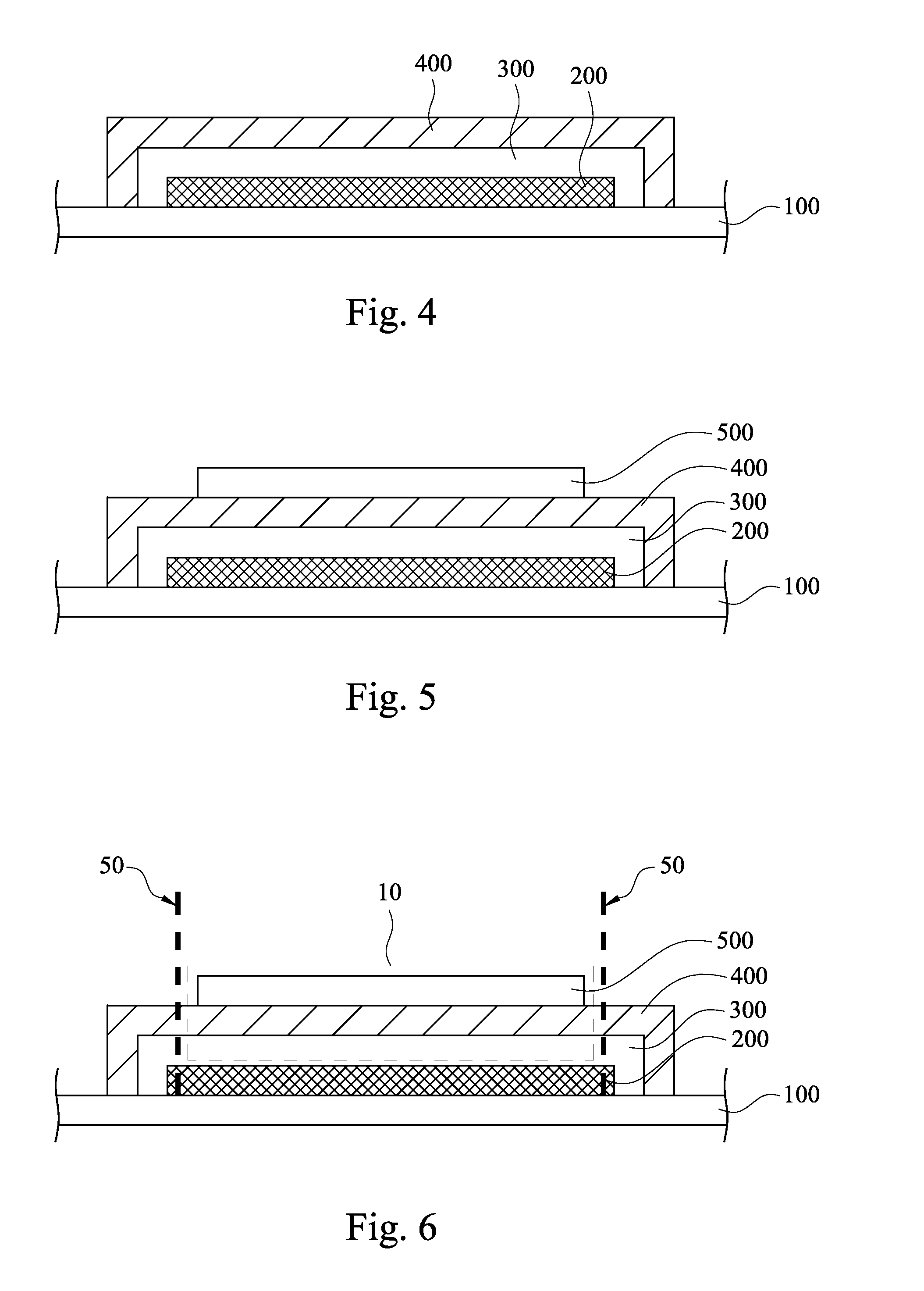
[0028]FIGS. 1 to 7 are cross-sectional views of a manufacturing method of an active device substrate according to one embodiment of the present invention. Reference is made to FIG. 1. A manufacturer can provide a supporting plate 100 first. The supporting plate 100 in this embodiment can be a rigid substrate, such as a glass, a quartz, or a silicon substrate.

[0029]Reference is made to FIG. 2. The manufacturer can form an organic de-bonding layer 200 on the supporting plate 100. The organic de-bonding layer 200 can be selected to completely or partially cover the supporting plate...


PUM

PropertyMeasurementUnit
thicknessaaaaaaaaaa
thicknessaaaaaaaaaa
electrostatic voltageaaaaaaaaaa

Abstract

An active device substrate includes a flexible substrate, an inorganic de-bonding layer, and at least one active device. The flexible substrate has a first surface and a second surface opposite to the first surface, wherein the first surface is a flat surface. The inorganic de-bonding layer covers the first surface of the flexible substrate, and the material of the inorganic de-bonding layer is metal, metal oxide or combination thereof. The active device is disposed on or above the second surface of the flexible substrate.

Description

RELATED APPLICATIONS[0001]This application claims priority to Taiwan Application Serial Number 102115623, filed May 1, 2013, which is herein incorporated by reference.BACKGROUND[0002]1. Technical Field[0003]The present disclosure relates to an active device substrate.[0004]2. Description of Related Art[0005]Recently, a new display with a flexible active device substrate has been lunched in the market. Because of its flexibility, the display device may replace the traditional papers or billboards.[0006]In the manufacturing process of the flexible active device substrate, it is convenient to fix a flexible substrate on a glass plate and then dispose active devices on the flexible substrate to form the flexible active device substrate. Afterwards, the flexible active device substrate is separated from the glass plate. However, when the attractive forces between the flexible substrate and the glass plate is too large, it is difficult to completely separate the flexible substrate and the...

Claims


Application Information

Patent Timeline
Patent Type & Authority Applications(United States)
IPC IPC(8): H01L21/78H01L33/02H01L29/12H01L29/04
CPCH01L21/78H01L33/02H01L29/12H01L29/04H01L27/1266Y02E10/549H01L21/7813Y02P70/50H10K71/80H10K77/111H10K2102/311H10K59/873H10K59/87H10K50/84H10K50/844H10K59/122H05K1/028H05K1/0353H05K1/181H05K2201/032
Inventor KE, TSUNG-YING
Owner AU OPTRONICS CORP
Why Eureka
Try Eureka