Roller bearing

a roller bearing and roller technology, applied in the field of roller bearings, can solve the problems of easy damage, and achieve the effect of not easy to wear and minimize the friction resistance between rollers

Active Publication Date: 2014-11-06
HIWIN TECH
View PDF0 Cites 3 Cited by
  • Summary
  • Abstract
  • Description
  • Claims
  • Application Information

AI Technical Summary

Benefits of technology

[0007]The present invention has been accomplished under the circumstances in view. It is the main object of the present invention to provide a roller bearing, which minimizes friction resistance between rollers and raceway faces and does not wear easily when rotated at a high speed.
[0010]Thus, compared to the prior art roller bearing, the invention can cause less sliding friction but reduces its load capacity, due to shortened contact length between each roller 50 and the raceway faces 361;362 and 461;462, the roller bearing 20. It is a useful design for light loading in high speed circumstance.
[0011]Subject to the designed value of the ratio between the width of each raceway face and the diameter, the roller bearing of the present invention effectively reduces the sliding fiction between the rollers and the raceway faces slightly reduced the load capacity of the roller bearing. Thus, when compared to the prior art design, the roller bearing of the present invention does not wear easily during rotation at a high speed.

Problems solved by technology

If these roller bearings are used in a high speed device, they can be damaged easily due to a rapid rise in temperature.

Method used


Image

  • Roller bearing
  • Roller bearing
  • Roller bearing

Examples


Embodiment Construction

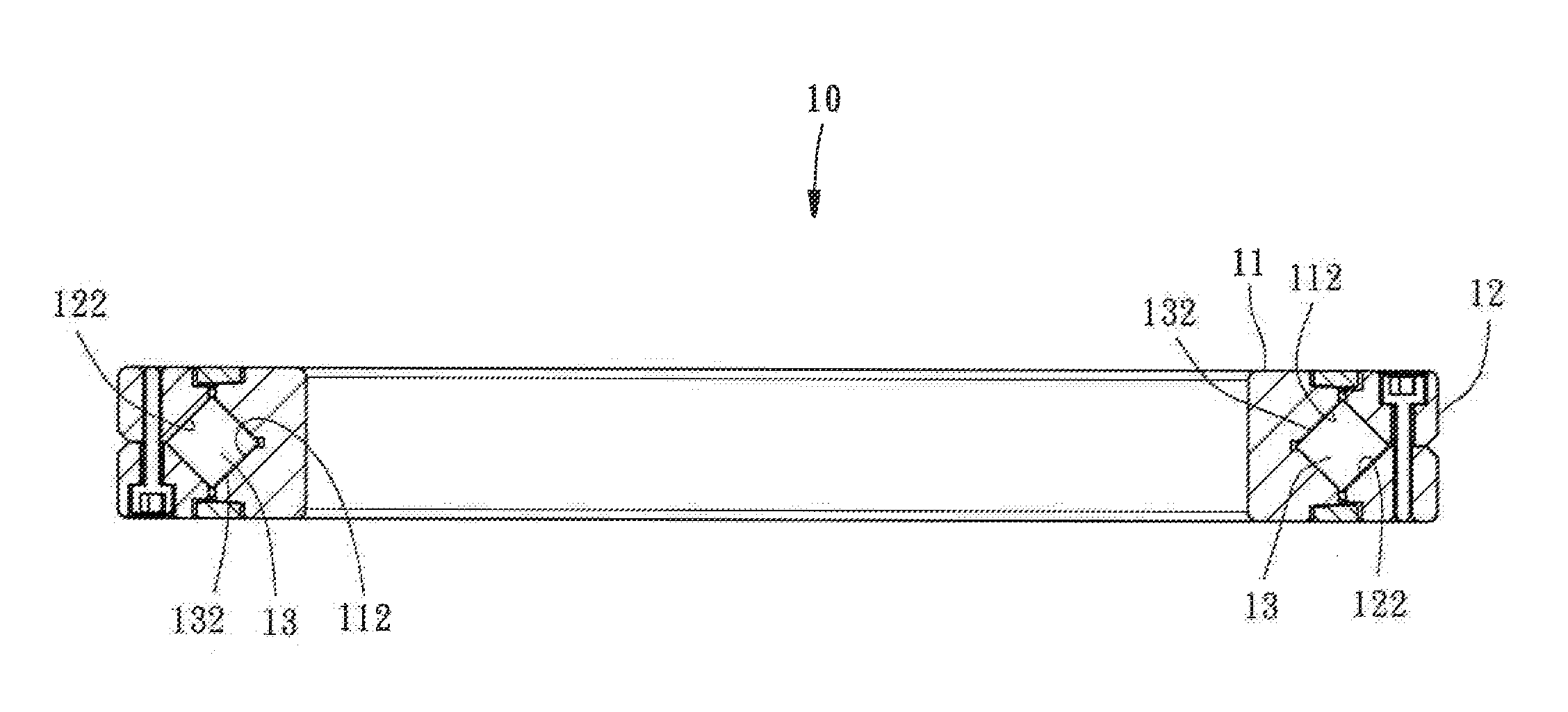
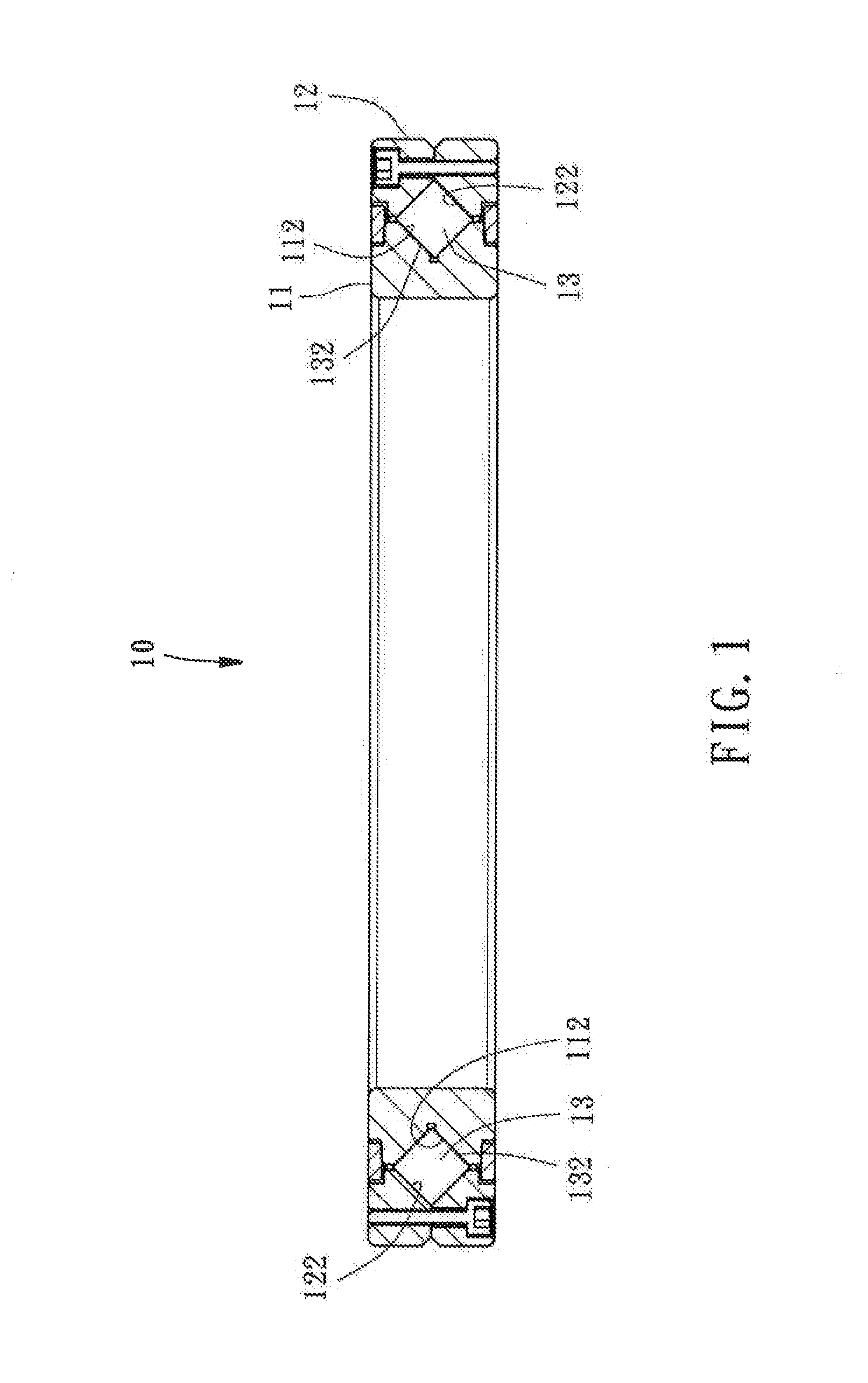
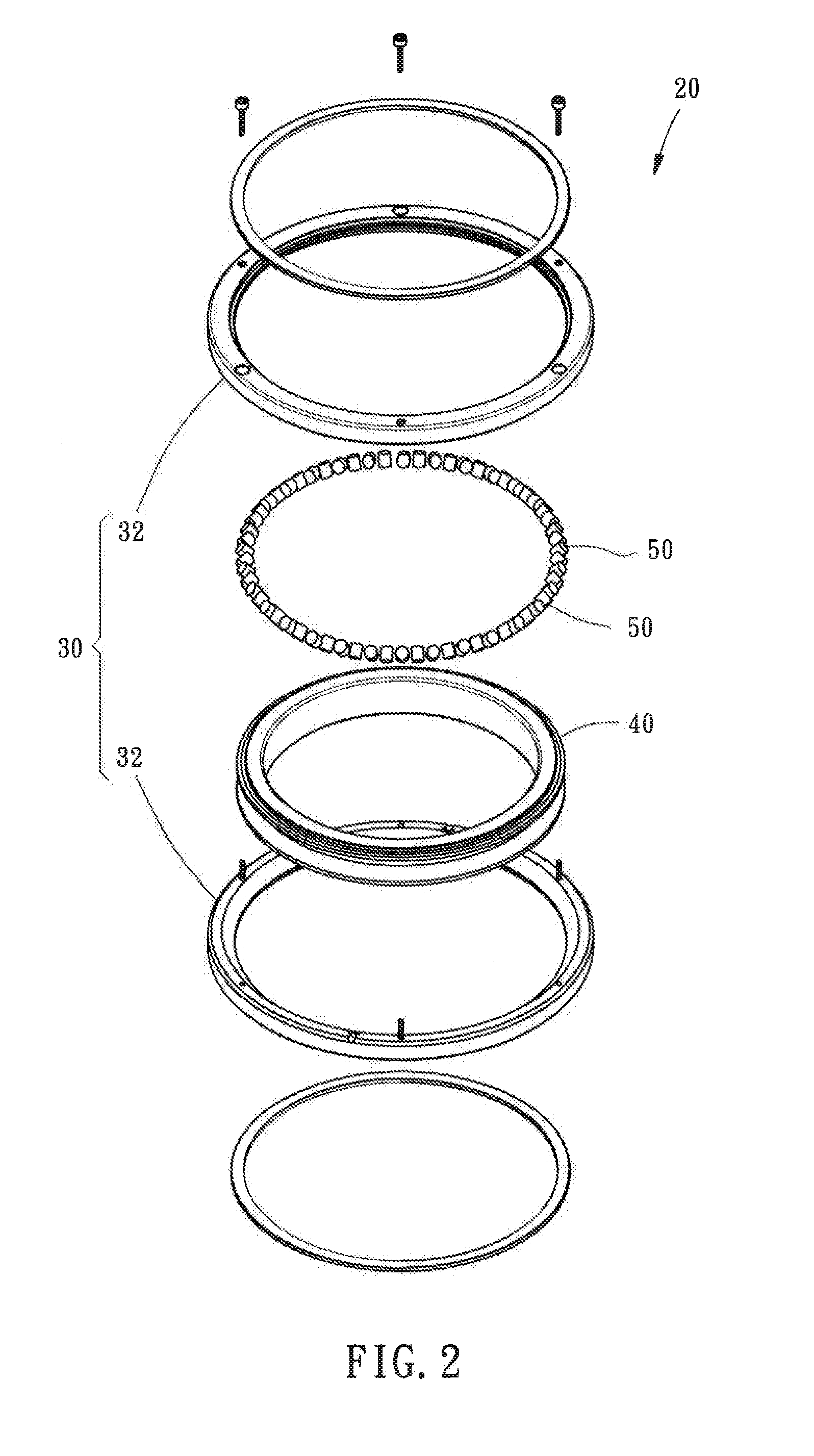
[0018]Referring to FIGS. 2 and 3, a roller bearing 20 in accordance with a first embodiment of the present invention is shown. As illustrated, the roller bearing 20 comprises an outer race 30, an inner race 40, and a plurality of rollers 50.

[0019]In this embodiment, the outer race 30 is formed of two ring-shaped halves 32 that are fixedly fastened together. As shown in FIG. 4, the outer race 30 comprises an inner surface 34, and a rolling channel 36 curved inward in the inner surface 34. The rolling channel 36 has a V-shaped cross section, defining two raceway faces 361 and 362 that are abutted at right angles, a groove 364 located in between the two raceway faces 361 and 362 and curved inward from the two raceway faces 361 and 362, and two notches 365 and 366 respectively located between the two raceway faces 361 and 362 and the inner surface 34.

[0020]The inner race 40 comprises an outer surface 44, and a rolling channel 46 curved inward in the outer surface 44. The rolling channel...


PUM


Abstract

A roller bearing, includes an outer race and an inner race coupled together and rotatable relative to each other, the inner and outer race each defining therein a respective rolling channel, each rolling channel defining two raceway faces abutted at right angles, and rollers accommodated in the rolling channels of the inner and outer races and rotatably kept in contact with the raceway faces of the inner and outer races. The roller bearing is characterized in that the inner and outer races each define a groove between the respective two raceway faces thereof; the ratio between the width of each raceway face and the diameter of each roller is ≧0.45 and ≦0.62, thus, the friction resistance between the rollers and the raceway faces is minimized, and therefore, the roller bearing does not wear easily when rotated at a high speed.

Description

BACKGROUND OF THE INVENTION[0001]1. Field of the Invention[0002]The present invention relates to bearing technology and more particularly, to a roller bearing, which has low sliding friction.[0003]2. Description of the Related Art[0004]Referring to FIG. 1, a conventional roller bearing 10 is known comprising an inner race 11, an outer race 12, and a plurality of rollers 13 rotatably accommodated between the inner race 11 and the outer race 12. The inner race 11 and the outer race 12 each define therein two raceway faces 112;122 abutted at right angles. Each roller 13 has the cylindrical surface 132 thereof rotatably kept in contact with one raceway face 112 of the inner race 11 and one raceway face 122 of the outer race 12, allowing the inner race 11 and the outer race 12 to be fastened together and rotatable relative to each other. Because rolling contact causes less friction resistance, the inner race 11 and the outer race 12 can be smoothly rotated relative to each other, and a l...

Claims


Application Information

Patent Timeline
Patent Type & Authority Applications(United States)
IPC IPC(8): F16C33/58
CPCF16C33/585F16C19/362F16C2240/40
Inventor KUO, CHANG-HSIN
Owner HIWIN TECH
Why Eureka
Try Eureka