High intensity light-emitting diode luminaire assembly

a light-emitting diode and array technology, applied in the direction of lighting and heating apparatus, semiconductor devices for light sources, lighting support devices, etc., can solve the problems of reducing led lifespan, reducing led lifespan, and reducing graceful degradation, so as to achieve constant led color temperature and/or color rendering index, the effect of reducing photon emission

Active Publication Date: 2014-11-13
SIGNIFY HLDG BV
View PDF14 Cites 56 Cited by
  • Summary
  • Abstract
  • Description
  • Claims
  • Application Information

AI Technical Summary

Benefits of technology

[0050]A method for maintaining a constant LED color temperature and / or a color rendering index in a lighting assembly (e.g., a HILL assembly) is also provided. The method can comprise the steps of using constant drive current, thereby decreasing photon emissions; and varying pulse width modulation (PWM).

Problems solved by technology

Although metal clad circuit cards known in the art, such as metal core printed circuit boards (MCPCB) can also be used, their use is less preferred, since they have a much greater cost than FR4 circuit boards.
First, this allows for graceful degradation as the array ages.
Second, the LED array does not experience hot spots that reduce LED lifespan.
As the string heats up, the LEDs' voltage potential drops, which in turn causes the LEDs to consume more current from the cooler strings.
This effect is known in the art as “thermal runaway” and causes LED arrays to fail prematurely.
Prior art luminaires reduce off-angle glare through the addition of a spun metal or refractive plastic shield, which is an additional cost.
These shields are relatively large and totally block off-angle glare but do not block the dispersion of the light source, thus wasting off-angle light output of the device.
This permits LEDs 162 to run continuously at only 80° C. or lower, whereas prior art systems being driven at such high light outputs must run at greater than 100° C. and are therefore prone to thermal runaway and failure.
This ability to vary the output voltage to a minimal value decreases the power loss of those strings that require less voltage across the LEDs.
The other strings that require less voltage need to dissipate the excess power created by the high voltage setting which leads to inefficient and less reliable designs.
This allows the advantage of using a commercially available 0-10V dimmer switch, but such a switch does not provide a pulse width modulation (PWM) output.

Method used


Image

  • High intensity light-emitting diode luminaire assembly
  • High intensity light-emitting diode luminaire assembly
  • High intensity light-emitting diode luminaire assembly

Examples


first embodiment

5.1. High Intensity LED Luminaire (HILL) Assembly—First Embodiment

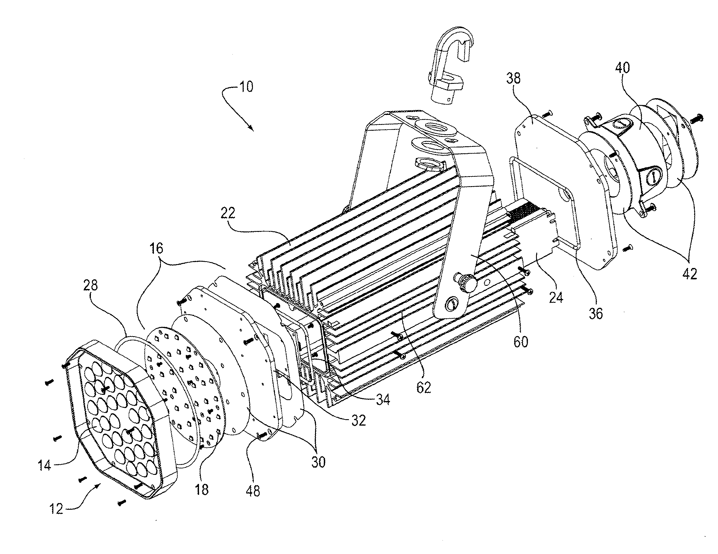
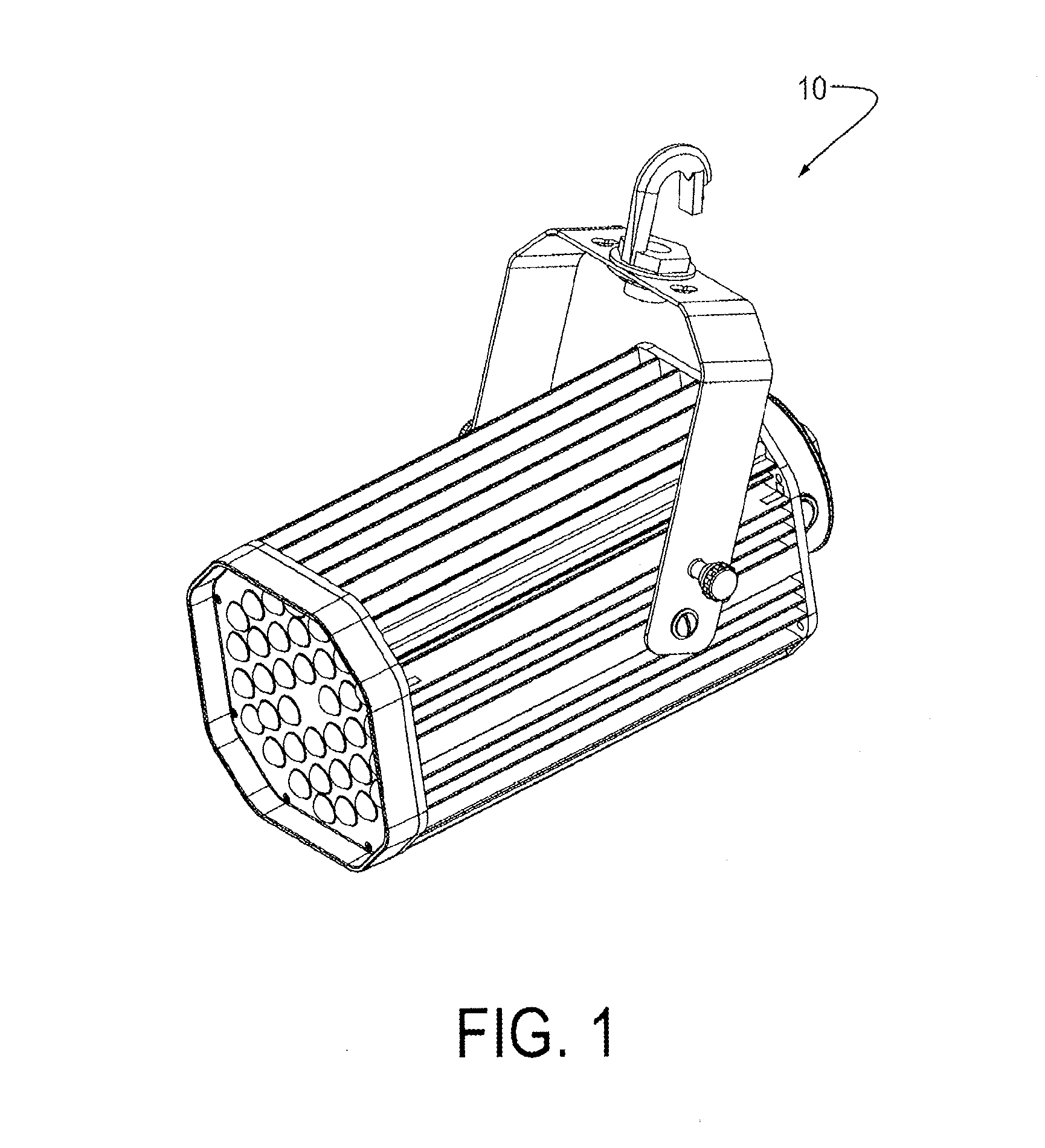
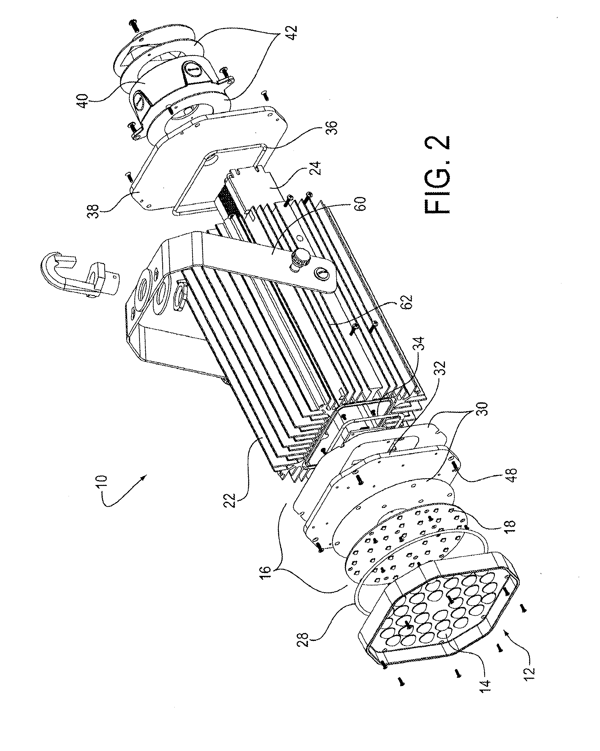
[0084]Referring now to FIGS. 1-16, a first embodiment 10 of a HILL assembly in accordance with the present invention comprises at least a secondary lens element 12 comprising a plurality of CCLs 14; a LED module 16, comprising a plurality of LEDs 18 equal in number to the number of CCLs 14, positioned in a first LED array 20; a heatsink (also referred to herein as a heatsink housing) 22; and a power supply 24 disposed within heatsink housing 22. Embodiment 10 further comprises a first O-ring 28; first and second thermal gaskets 30; an interface plate 32; a second O-ring 34 for sealing heatsink housing 22 at the front end; a third O-ring 36 for sealing heatsink housing 22 at the rear end; a back plate 38; a junction box 40; and sealing gaskets 42.

[0085]Lens Element

[0086]HILL assembly 10 comprises a single secondary lens element 12 (FIGS. 2-3) with one or more CCLs 14 integrated into the lens element. Lens element 12 is...

second embodiment

5.2. High Intensity LED Luminaire (HILL) Assembly—Second Embodiment

[0113]A HILL assembly is also provided that is based on a modular design. In various embodiments, the HILL assembly can comprise modular lensing provided by, e.g., a lens matrix, a plurality of LED modules or modular LED arrays, joiner brackets that allow for modularity and custom angular positioning of light output, modular heatsink housing(s) and high power modular circuits (that can operate, for example, at high temperatures).

[0114]The modular lensing allows for mixing and matching of distribution patterns, which can provide precise, including but not limited to custom, optical controls.

[0115]The LED modules or modular LED arrays can have a shared cover design that allows for stacking or joining of multiple modules without the need for fasteners. An advantage of this design is that it does not interfere with the function of the heatsink. The design can allow heat to be pulled with convectional heat transfer.

[0116]...


PUM


Abstract

A low-cost, efficient, high intensity LED luminaire (HILL) assembly for use indoors or outdoors in wet, damp, or dry environments. In various embodiments, the HILL assembly can be powered by a universal AC or a DC electrical supply and can operate in a temperature range from about −40° C. to about +85° C. The HILL assembly can include a lens element comprising one or more concavo-convex lenses; an interchangeable LED module comprising a plurality of LEDs positioned in a LED array; and a heatsink housing containing a power supply for the LEDs. The HILL assembly can optionally comprise a circuit board for the LED array that employs thermal via technology, a lens with a frosted lip for attenuating the light source as seen from an angle, and/or a sensor for sensing an environmental parameter of interest. Driver circuitry and the LEDs are preferably mounted directly on a common circuit board.

Description

CROSS-REFERENCE TO RELATED APPLICATIONS[0001]This application claims priority to and the benefit of co-pending U.S. provisional patent applications Ser. No. 61 / 570,072, entitled “High Intensity Light-Emitting Diode (LED) Luminaire and Methods for Making Same,” filed Dec. 13, 2011, and Ser. No. 61 / 712,226, entitled “High Intensity Light-Emitting Diode Luminaire Assembly,” filed Oct. 10, 2012, each of which is incorporated herein by reference in its entirety.1. TECHNICAL FIELD[0002]The present invention relates to high intensity light-emitting diode (LED) array technology. The invention further relates high intensity LED luminaires and high intensity LED luminaire (HILL) assemblies and methods for making them.2. BACKGROUND OF THE INVENTION[0003]High intensity light-emitting diode (LED) array technology is currently used to provide lighting in a wide range of applications in which the user needs high intensity illumination.[0004]One drawback of existing high intensity LED luminaire (HI...

Claims


Application Information

Patent Timeline
Patent Type & Authority Applications(United States)
IPC IPC(8): F21V29/00F21K99/00F21V23/00H05B44/00
CPCF21V29/2206F21V23/009F21K9/50F21Y2105/001F21V5/007F21V21/30F21K9/00F21S2/00F21V15/013F21V21/08F21V23/0464F21V23/0471F21V29/70F21V29/74F21V29/773F21Y2105/10F21K9/60F21Y2115/10F21K9/69F21V29/75Y02B20/40H05B45/345H05B45/35H05B45/56H05B45/52H05B45/375H05B45/46H05B47/16F21V23/005F21Y2101/00F21V29/89F21V3/049F21V17/12F21V21/14F21V31/005
Inventor NOLAN, CHRISTOPHERCASPER, JOSEPHWITKOWSKI, JOSEPHHULL, JONATHAN
Owner SIGNIFY HLDG BV
Why Eureka
Try Eureka