Automatic electric punching apparatus

a technology of electric punching and electric motor, which is applied in the direction of metal working apparatus, etc., can solve the problems of high manufacturing cost, complex structure, and inability to easily perform punching operations, and achieve the effect of convenient punching operations, simplified electric structure and reduced manufacturing costs

Active Publication Date: 2014-11-20
LEE YONG WOO
View PDF4 Cites 6 Cited by
  • Summary
  • Abstract
  • Description
  • Claims
  • Application Information

AI Technical Summary

Benefits of technology

[0009]Preferably, a balance rod is fixedly installed downward at a predetermined point of a lower surface of the upper block and a cylinder hole is formed in the lower block corresponding to the balance rod so that the upper block is prevented from being arbitrarily moved through a guide operation of the balance rod and the cylinder hole when the upper block is moved upward and downward.
[0013]As described above, according to the present invention, since a screw punch blade having a specific structure is automatically rotated and lowered to automatically punch documents or paper sheets as a motor is driven according to manipulation of a switch on a front side of a body, a user can very conveniently perform a punching operation without using a separate push handle.
[0014]In addition, as the punching apparatus has a very simplified electric structure, manufacturing costs can be reduced by simplifying components and an assembly process thereof. Further, an outer design is so appealing that it can meet a satisfaction of a user.

Problems solved by technology

Then, an electric punching apparatus according to the related art generally employs a heavy motor, and accordingly, has a complex structure and consumes high manufacturing costs.
Further, since most electric punching apparatuses are of one hole type and operated in a compulsory press manner or a pipe type punch blade rotation manner, a punching operation cannot be easily performed.
In addition, although a punching apparatus for punching a hole in various documents or paper sheets generally has a push handle at an outside of a body thereof so that a user can push down the handle with his or her hands to manually lower a punching unit, it is very troublesome to use the punching apparatus.
Although automatic punching apparatuses are used as an alternative, most of them are suitable for industrial mass punching and cannot be used for the purposes of offices or homes.

Method used


Image

  • Automatic electric punching apparatus
  • Automatic electric punching apparatus
  • Automatic electric punching apparatus

Examples


Embodiment Construction

)

[0020]In describing the preferred embodiment of the present invention, reference will be made herein to FIGS. 1-4B of the drawings in which like numerals refer to like features of the invention.

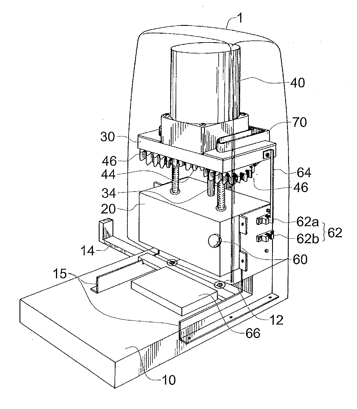
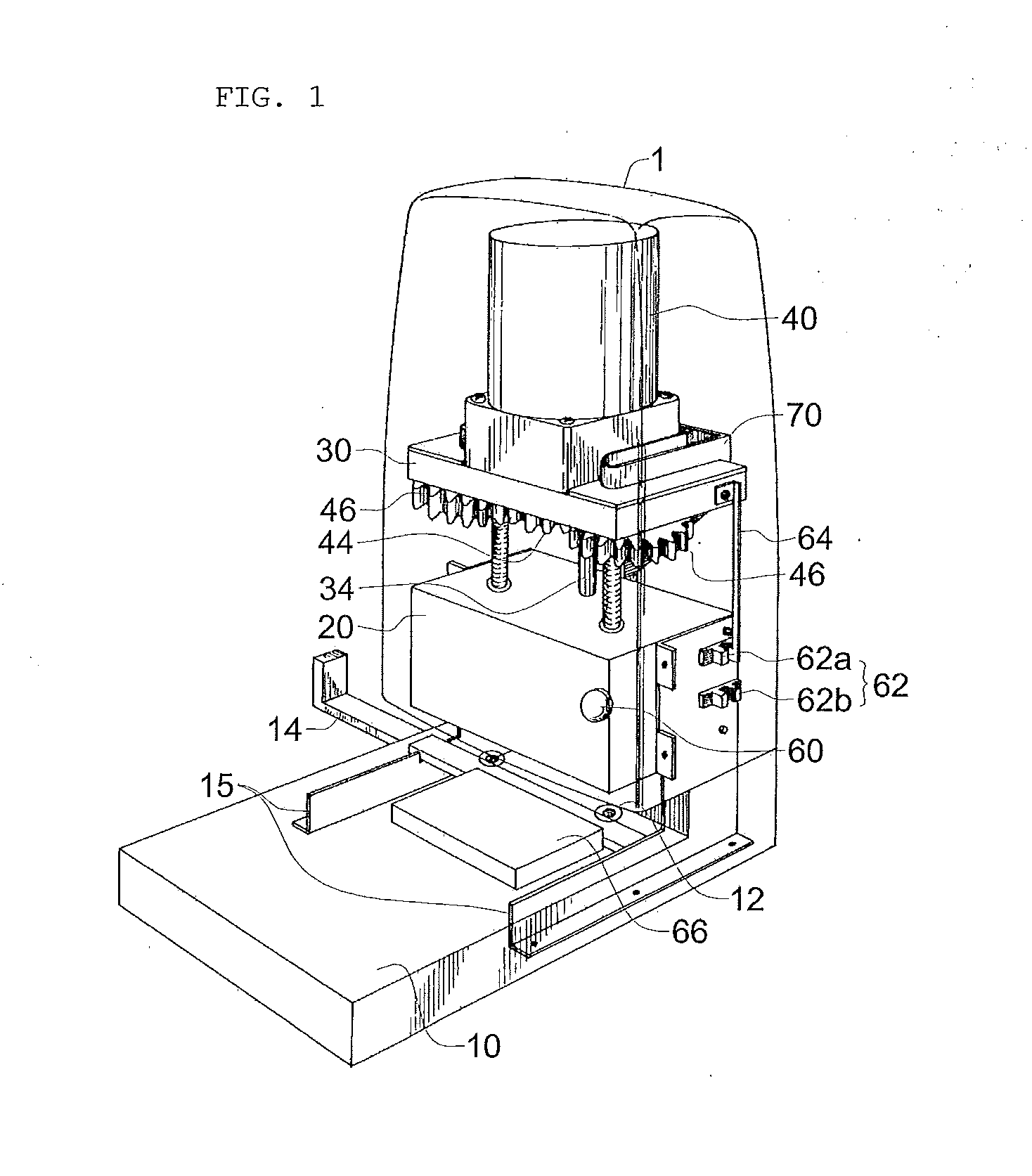
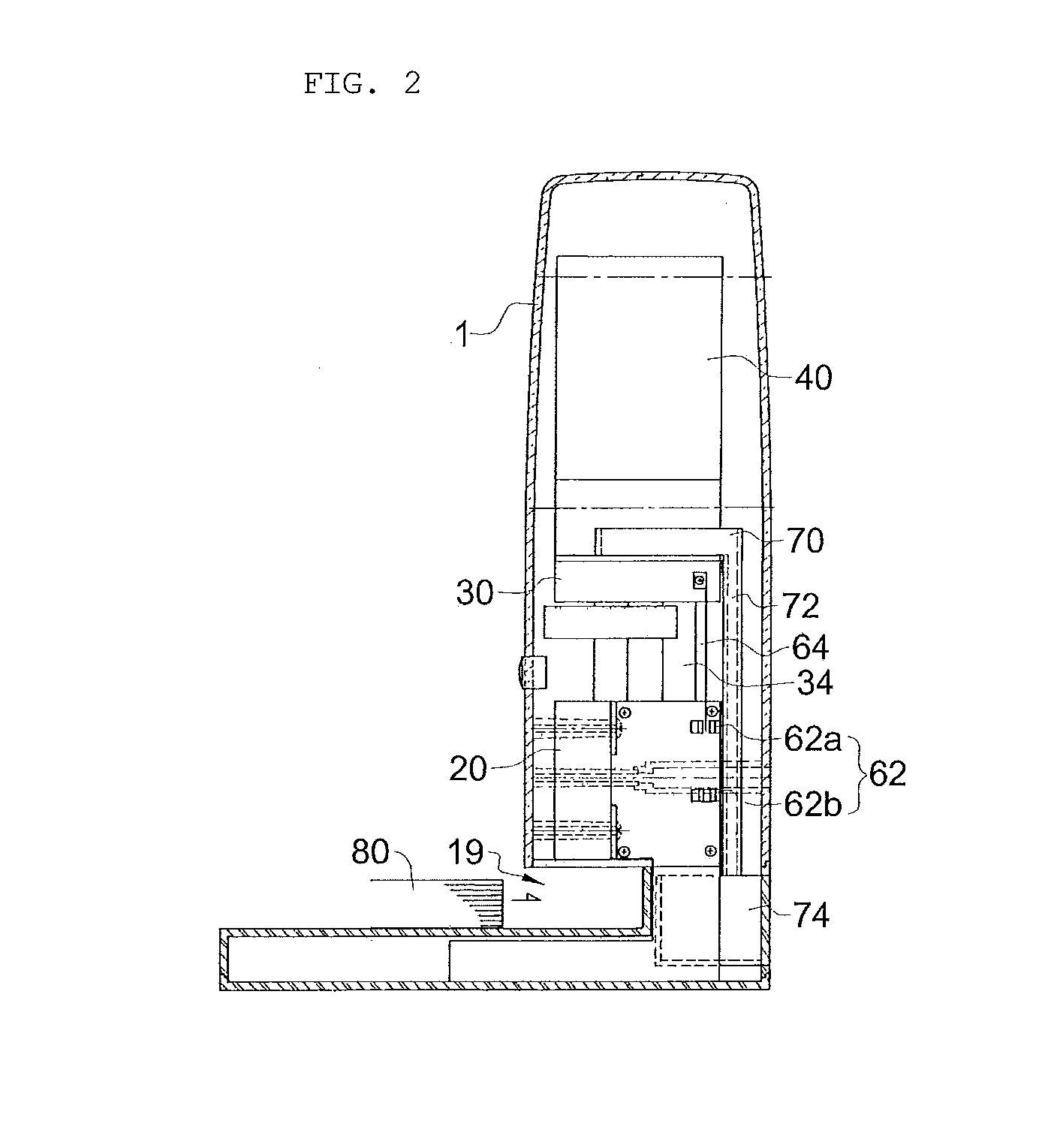
[0021]FIG. 1 is a perspective view illustrating a configuration of an automatic electric punching apparatus according to the present invention. FIG. 2 is a side view illustrating the configuration of the automatic electric punching apparatus according to the present invention. FIG. 3 is a plan view illustrating the configuration of the automatic electric punching apparatus according to the present invention. FIGS. 4A and 4B are sectional views illustrating an operation of the automatic electric punching apparatus according to the present invention.

[0022]First, in the automatic electric punching apparatus according to the present invention, a pair of screw punches 50 are automatically rotated through driving of a motor 40 and is lowered by means of a screw thread as a user manipulates a switc...


PUM

PropertyMeasurementUnit
lengthaaaaaaaaaa
shapeaaaaaaaaaa
heightaaaaaaaaaa

Abstract

The present disclosure provides an automatic electric punching apparatus that can automatically punch documents or paper sheets by lowering a screw punch blade by means of a screw while being rotated in conjunction with driving of a motor due to switching.

Description

BACKGROUND OF THE INVENTION[0001]1. Field of the Invention[0002]The present invention relates to an automatic electric punching apparatus, and more particularly, to an automatic electric punching apparatus that can automatically and conveniently perform a punching operation on a plurality of documents or paper sheets by providing the punching apparatus with a specific structure by means of a small-sized motor and a screw punch blade.[0003]2. Description of Related Art[0004]In general, a standard binder or a file is used to collect a plurality of documents or paper sheets for a long time, in which case in order to file the documents or paper sheets by using the binder or file, a pair of holes are punched at a predetermined interval at predetermined locations of the documents or paper sheets by using a punching apparatus.[0005]Then, an electric punching apparatus according to the related art generally employs a heavy motor, and accordingly, has a complex structure and consumes high ma...

Claims


Application Information

Patent Timeline
Patent Type & Authority Applications(United States)
IPC IPC(8): B26D5/08B26D7/18B26F1/02
CPCB26D5/086B26D7/18B26F1/02B26D2007/0018Y10T83/141Y10T83/222Y10T83/531Y10T83/544Y10T83/8828Y10T83/8847Y10T83/9423B26F1/14B26F1/34
Inventor LEE, YONG-WOO
Owner LEE YONG WOO
Why Eureka
Try Eureka