Method for self-testing notification appliances in alarm systems

a notification appliance and alarm system technology, applied in the field of alarm systems, can solve the problem that evaluating the functionality of notification appliances in this manner can be extremely burdensom

Active Publication Date: 2014-11-20
JOHNSON CONTROLS TYCO IP HLDG LLP
View PDF8 Cites 39 Cited by
  • Summary
  • Abstract
  • Description
  • Claims
  • Application Information

AI Technical Summary

Benefits of technology

[0006]In view of the foregoing, it would be advantageous to provide improved means for self-testing notification appliances in an alarm system wherein such means are able to discriminate between the output of the notification features of a notification appliance that is being tested and other, ambient sound or light.

Problems solved by technology

Occupants of the building may thereby be notified of potentially hazardous conditions and may evacuate the building or take other action before being harmed.
Evaluating the functionality of notification appliances in this manner can be extremely burdensome, as it can be time-consuming and arduous to physically visit every notification appliance in a building.
This is especially true for alarm systems that include a large number of notification appliances and / or that include notification appliances that are installed in parts of a building that are not readily accessible.
Therefore, when the output of such notification features is measured during self-testing, a particularly strong source of ambient sound or light produced by a source other than the notification features could result in a so-called “false positive.” That is, a notification appliance having a defective notification feature that would normally fail a self-test may measure ambient sound or light generated by a nearby device, and may mistakenly interpret such sound or light as output generated by its own notification features, thereby causing the notification appliance to erroneously record a “pass” result for the self-test.

Method used


Image

  • Method for self-testing notification appliances in alarm systems
  • Method for self-testing notification appliances in alarm systems
  • Method for self-testing notification appliances in alarm systems

Examples


Embodiment Construction

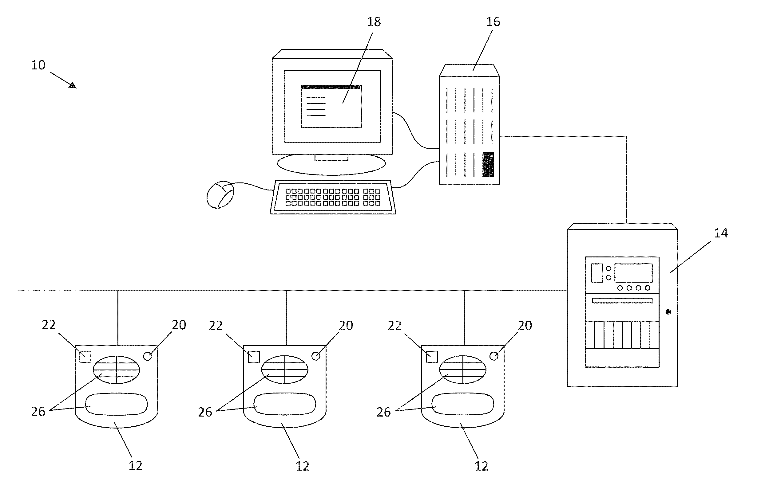
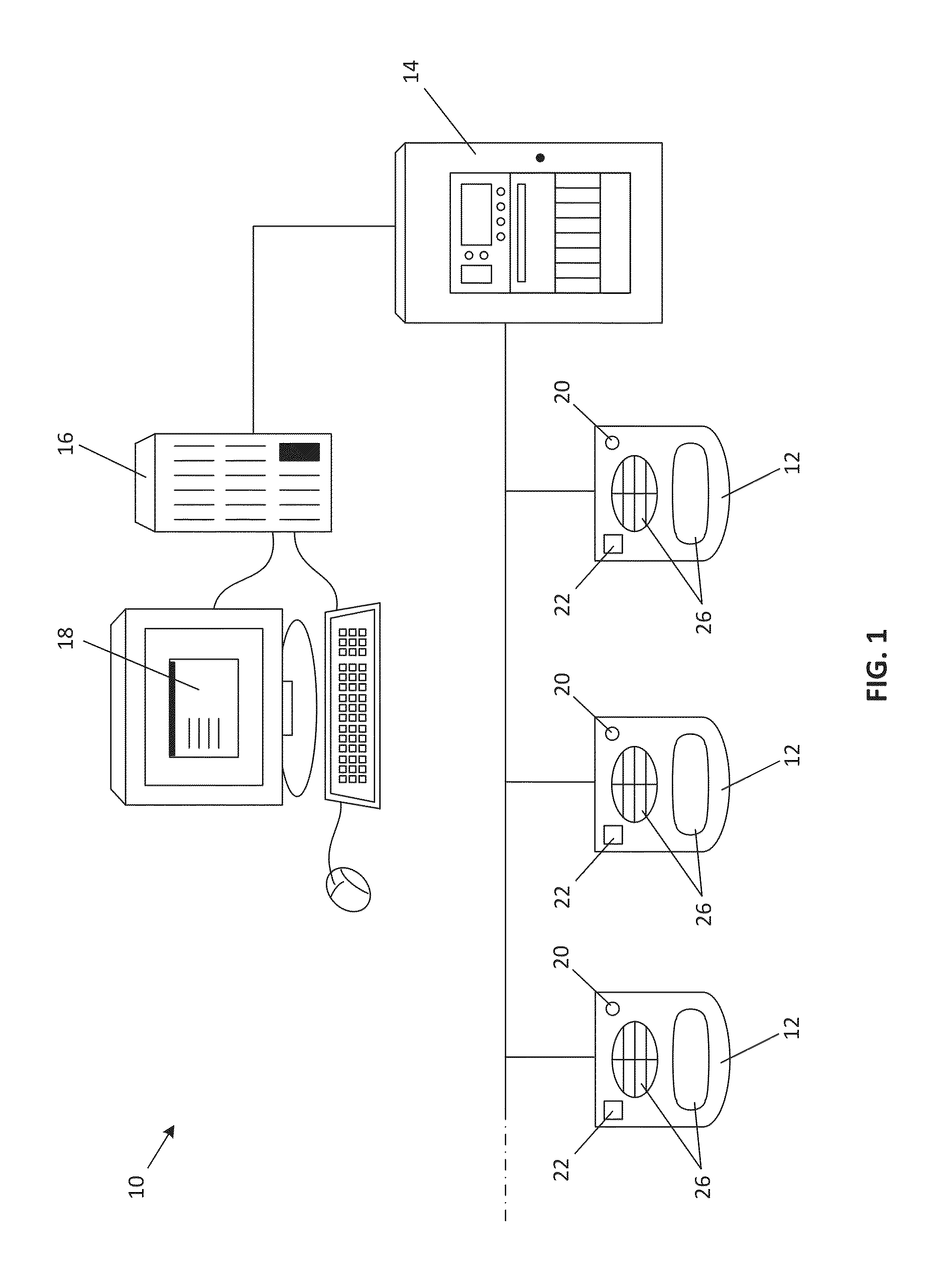
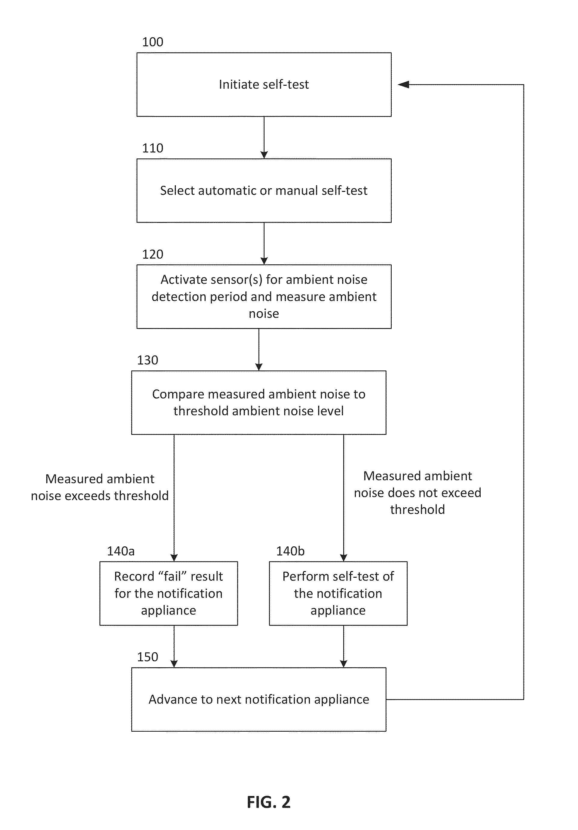
[0011]A method for self-testing notification appliances in accordance with the present disclosure will now be described more fully hereinafter with reference to the accompanying drawings, in which preferred embodiments of the invention are shown. The disclosed methods, however, may be embodied in many different forms and should not be construed as limited to the embodiments set forth herein. Rather, these embodiments are provided so that this disclosure will be thorough and complete, and will fully convey the scope of the invention to those skilled in the art. In the drawings, like numbers refer to like elements throughout.

[0012]It will be appreciated by those of ordinary skill in the art that the method described herein may be implemented in virtually any type of alarm or monitoring system, including, but not limited to, fire alarm systems, burglar alarm systems, surveillance systems, air quality monitoring systems, inventory monitoring systems, etc., or any combination thereof, su...


PUM


Abstract

A method for self-testing notification appliances in an alarm system, including the steps of measuring ambient noise at a notification appliance, comparing the measured ambient noise to a threshold ambient noise level, and performing a self-test of the notification appliance if the measured ambient noise does not exceed the threshold ambient noise level. The method may further include the step of recording a fail result for the notification appliance if the measured ambient noise exceeds the threshold ambient noise level. Performing the self-test of the notification appliance may include the steps of activating a notification feature of the notification appliance, measuring output of the notification feature, comparing the measured output to a predefined value, recording a pass result for the notification appliance if the measured output exceeds the predefined value, and recording a fail result for the notification appliance if the measured output does not exceed the predefined value.

Description

FIELD OF THE DISCLOSURE[0001]The disclosure relates generally to the field of alarm systems, and more particularly to an improved method for self-testing notification appliances in alarm systems.BACKGROUND OF THE DISCLOSURE[0002]Alarm systems, such as fire alarm systems, typically include a plurality of notification appliances (e.g. horn / strobe units), that are installed throughout a monitored building and that are configured to be activated upon the detection of an alarm condition, such as the presence of fire or smoke. Occupants of the building may thereby be notified of potentially hazardous conditions and may evacuate the building or take other action before being harmed. It is therefore critically important that the notification appliances of alarm systems always be in good working order.[0003]Governmental entities may require that notification appliances, and particularly those of fire alarm systems, be tested periodically to verify that such appliances are operating properly....

Claims


Application Information

Patent Timeline
Patent Type & Authority Applications(United States)
IPC IPC(8): G08B29/12
CPCG08B29/12H04R29/007G08B29/126
Inventor PICCOLO, III, JOSEPHDAHLSTROM, DAVID
Owner JOHNSON CONTROLS TYCO IP HLDG LLP
Why Eureka
Try Eureka