Method and system for providing backward compatibility

a backward compatibility and controller technology, applied in the field of computer video gaming, can solve the problems of limited functionality of the controller, no system seems to have surmounted the challenges involved, and it is difficult or impossible to confuse which controllers, so as to achieve a lot of flexibility in controlling the virtual environmen

Inactive Publication Date: 2014-11-20
AILIVE
View PDF3 Cites 4 Cited by
  • Summary
  • Abstract
  • Description
  • Claims
  • Application Information

AI Technical Summary

Benefits of technology

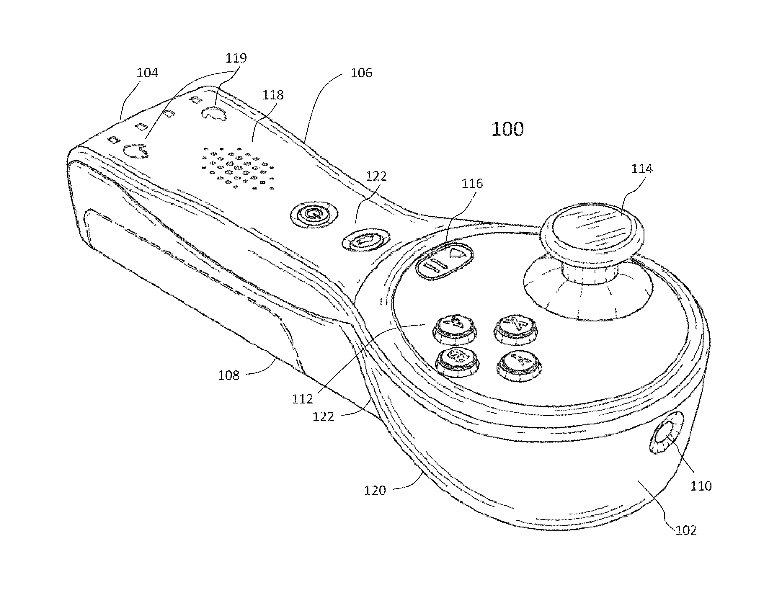
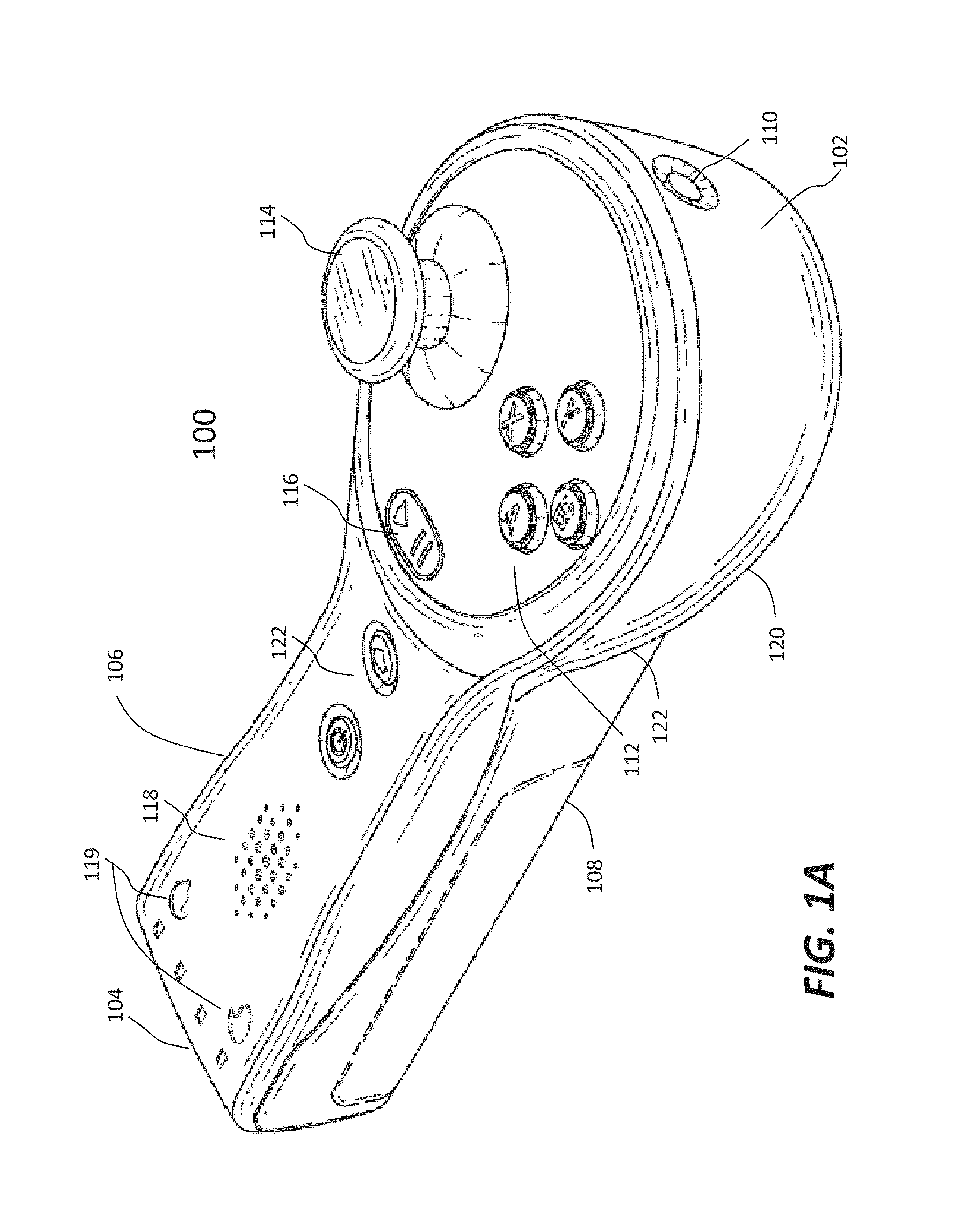
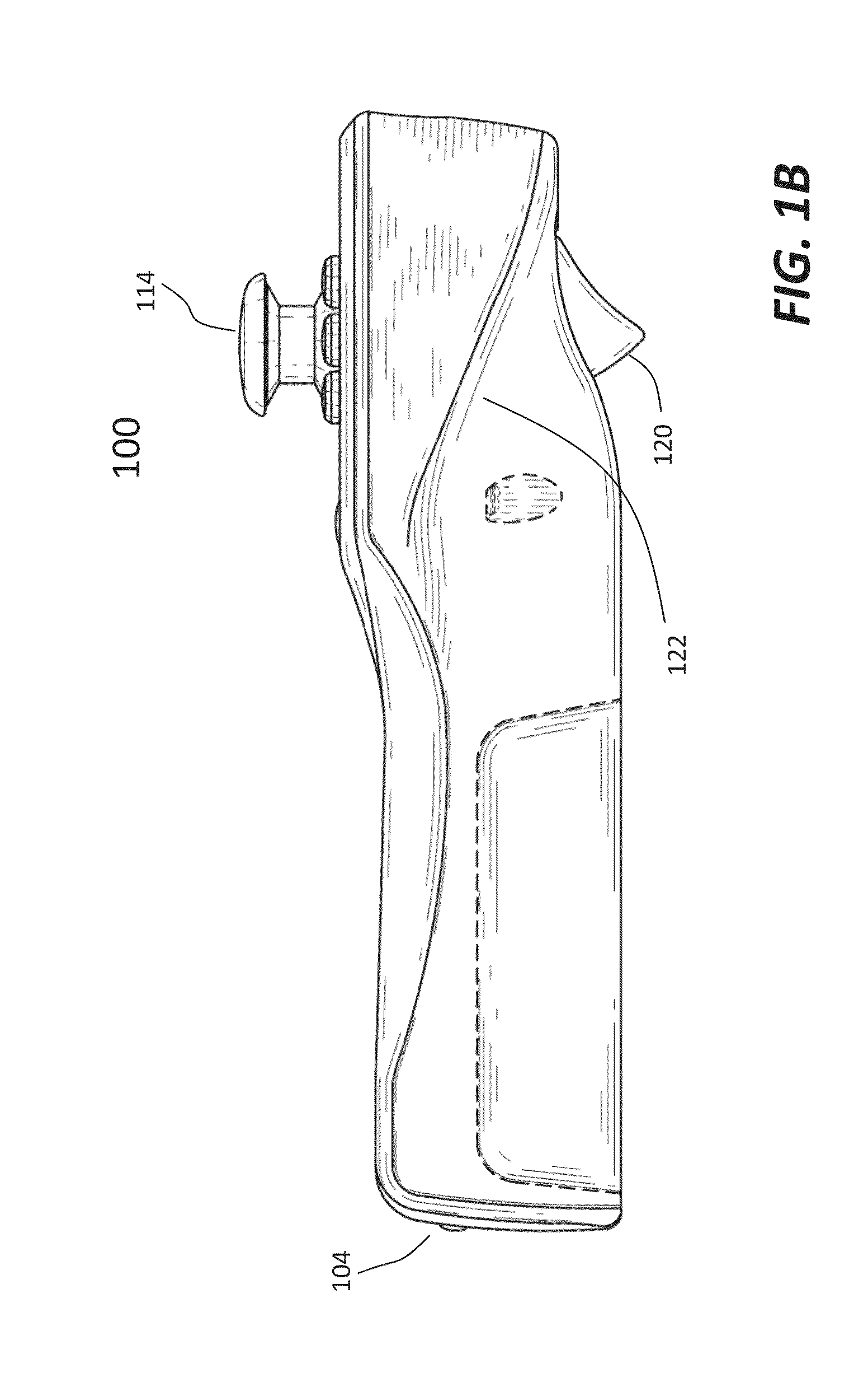
[0013]The present invention generally pertains to a controller with full functionalities in a sense that the controller does not need any attachment and is operable with one hand to fully control an interactive environment being shown. The sensing signals from the controller are sufficient to derive orientations and positions of the controller in six degrees of freedom. According to one aspect of the present invention, when two of such controllers are being used by one user, one embodiment of the present invention is able to distinguish which hand is holding which controller without the intervention of the user. To allow the controller to work with existing game systems, another aspect of the present invention is to provide the compatibility of the controller to an old controller.
[0016]According to still another embodiment, it is a method for providing compatibility of a first controller to a second controller, the method comprises: receiving inertial sensor data from the first controller; and transforming the inertial sensor data to masquerade as though the inertial sensor data were coming from a set of inertial sensors in the second controller. The transforming of the inertial sensor data comprises: replicating operational characteristics of the inertial sensor data of the second controller, and relocating virtually the inertial sensor data to appear as though the inertial sensor data were generated from inertial sensors located in a certain location in the first controller responsive to a certain location of the inertial sensors in the second controller. Depending on implementation, the operation of the transforming is executed in a driver for the first controller or a software module running on a processing unit configured to work with the second controller; and the transformed inertial sensor data from the first controller works robustly with motion recognizers and motion trackers built for the second controller.
[0019]One of the objects, features and advantages of the present invention is to provide a lot of flexibility in controlling a virtual environment. The use of the controllers as designed is applicable to a classic control by one user, one or two handed freeform motion control by one user, or a one-handed freeform motion control by two users.

Problems solved by technology

These types of controllers, however, are limited in the functionality they provide.
However, neither system seems to have surmounted the challenges involved with providing this functionality for their independently operable motion controller.
There are at least two key challenges in providing game controllers that are fully functional freeform controllers, meaning that they are: independently operable; motion sensitive; able to support motion recognition and motion tracking for one or both hands; and carry a full complement of buttons, triggers and analog sticks.
Second, the system must make it hard or impossible to confuse which controllers are in which hands or with which people to avoid frequent player frustration.
If the wrong hand picks up the wrong controller, the motion control results would be subtly wrong since, for example, the inertial data corresponding to a left-handed motion will not match that for a corresponding right-handed motion.
The resulting frustration would be analogous to having a TV remote control that works incorrectly half the time you pick it up.
Although most game controllers today make it clear which controller is connected to which port with an LED on the controller, none solves the significant technical problem of automatically detecting and displaying which hand is operating which controller in real time without user intervention.

Method used


Image

  • Method and system for providing backward compatibility
  • Method and system for providing backward compatibility
  • Method and system for providing backward compatibility

Examples


Embodiment Construction

[0032]The detailed description of the invention is presented largely in terms of procedures, steps, logic blocks, processing, and other symbolic representations that directly or indirectly resemble the operations of data processing devices coupled to networks. These process descriptions and representations are typically used by those skilled in the art to most effectively convey the substance of their work to others skilled in the art.

[0033]Reference herein to “one embodiment” or “an embodiment” means that a particular feature, structure, or characteristic described in connection with the embodiment can be included in at least one embodiment of the invention. The appearances of the phrase “in one embodiment” in various places in the specification are not necessarily all referring to the same embodiment, nor are separate or alternative embodiments mutually exclusive of other embodiments. Further, the order of blocks in process flowcharts or diagrams representing one or more embodimen...


PUM


Abstract

Techniques for providing compatibility between two different game controllers are disclosed. When a new or more advanced controller is introduced, it is important that such a new controller works with a system originally configured for an existing or old controller. The new controller may provide more functionalities than the old one does. In some cases, the new controller provides more sensing signals than the old one does. The new controller is configured to work with the system to transform the sensing signals therefrom to masquerade as though they were coming from the old controller. The transforming of the sensing signals comprises: replicating operational characteristics of the old controller, and relocating virtually the sensing signals to appear as though the sensing signals were generated from inertial sensors located in a certain location in the new controller responsive to a certain location of the inertial sensors in the old controller.

Description

CROSS-REFERENCE TO RELATED APPLICATION[0001]This is a continuation of co-pending U.S. application Ser. No. 12 / 910,818, entitled “Method and system for providing compatibility between two different controllers”, filed Oct. 24, 2010, now U.S. Pat. No. 8,795,078, which is a continuation-in-part of co-pending U.S. application Ser. No. 12 / 020,431, entitled “Self-Contained Inertial Navigation System for Interactive Control Using Movable Controllers”, filed Jan. 25, 2008, which is a continuation-in-part of the following applications: U.S. application Ser. No. 11 / 486,997, entitled “Generating Motion Recognizers for Arbitrary Motions”, filed Jul. 14, 2006, now U.S. Pat. No.: 7,702,608, U.S. application Ser. No. 11 / 820,207, entitled “Generating Motion Recognizers for Arbitrary Motions”, filed Jun. 18, 2007, now U.S. Pat. No. 7,636,645, and U.S. application Ser. No. 12 / 709,523, entitled “Systems and methods for utilizing personalized motion control in virtual environment”, filed Feb. 22, 2010....

Claims


Application Information

Patent Timeline
Patent Type & Authority Applications(United States)
IPC IPC(8): A63F13/00
CPCA63F13/00A63F2300/1043A63F2300/105A63F2300/6045G06F3/0346G06F3/0325A63F13/22A63F13/40A63F13/211A63F13/45
Inventor MUSICK, JR., CHARLESKAY, ROBERTPOWERS, III, WILLIAM ROBERTWILKINSON, DANAZHU, YOUDING
Owner AILIVE
Why Eureka
Try Eureka