
Cooking grate assembly and cooking apparatus

a technology of grate and cooking utensils, which is applied in the field of cooking utensils and grate assemblies, can solve the problems of shortening the life of the grate, affecting the cooking efficiency of the grate, and the majority of food support utensils used in infrared and other outdoor grills, so as to achieve substantially rust-free cooking and reduce or eliminate the occurrence of flare-ups

Active Publication Date: 2014-11-27
W C BRADLEY CO
View PDF1 Cites 3 Cited by
  • Summary
  • Abstract
  • Description
  • Claims
  • Application Information

AI Technical Summary

Benefits of technology

The present invention provides an improved cooking grate assembly and system that solves problems associated with flare-ups and grease / fat dripping. The grate assembly includes a lower grate element that reduces flare-ups and an upper grate element that is rust-free. The openings in the grate assembly are designed to allow grease and fat to drain through quickly while preventing them from inflaming or causing flare-ups. These improvements make the cooking process safer and efficient.

Problems solved by technology

However, there are various shortcomings and deficiencies which are often associated with many current infrared systems.
Even if formed of a common stainless steel or similar material, most food support grates heretofore used in infrared and other outdoor grills will begin to rust after a relatively short period of use.
This oxidation process not only shortens the life of the grate, but the particles and / or flakes of the oxidized rust material which form on the grate surface also adhere to the food product.
However, such materials are cost prohibitive for use in most grilling systems and / or are not well suited for grilling at high temperatures.
However, coating a cooking grate with such material can also be cost prohibitive for most grilling apparatuses.
Moreover, the application of such a coating to an infrared grate can clog any air flow openings through the grate surface and can create other problems and difficulties which will increase both the complexity and the cost of the manufacturing process.
Another serious deficiency encountered with current infrared cooking grates is their susceptibility to flare-ups caused by the ignition of fat and grease materials which collect on top of the grate during cooking.
Such flare-ups have a significant detrimental effect on the quality, consistency, reliability, and evenness of the cooking process.
Moreover, the collection of the fat and grease materials also interferes with and reduces the emission of infrared cooking energy from the grate.
However, in these prior two-piece grate designs and configurations, the nature and large size of the holes needed to quickly and effectively drain the grease and fat from the flat lower plate before it reaches ignition temperature would, in actuality, simply result in one flare-up problem being replaced with another.
Specifically, with the addition of holes in the lower plate of a sufficient size to achieve quick drainage, the prior two-piece assemblies would no longer be capable of arresting flames caused by the flare-up of the grease and fat beneath the grate.

Method used


Image

  • Cooking grate assembly and cooking apparatus
  • Cooking grate assembly and cooking apparatus
  • Cooking grate assembly and cooking apparatus

Examples


embodiment 2

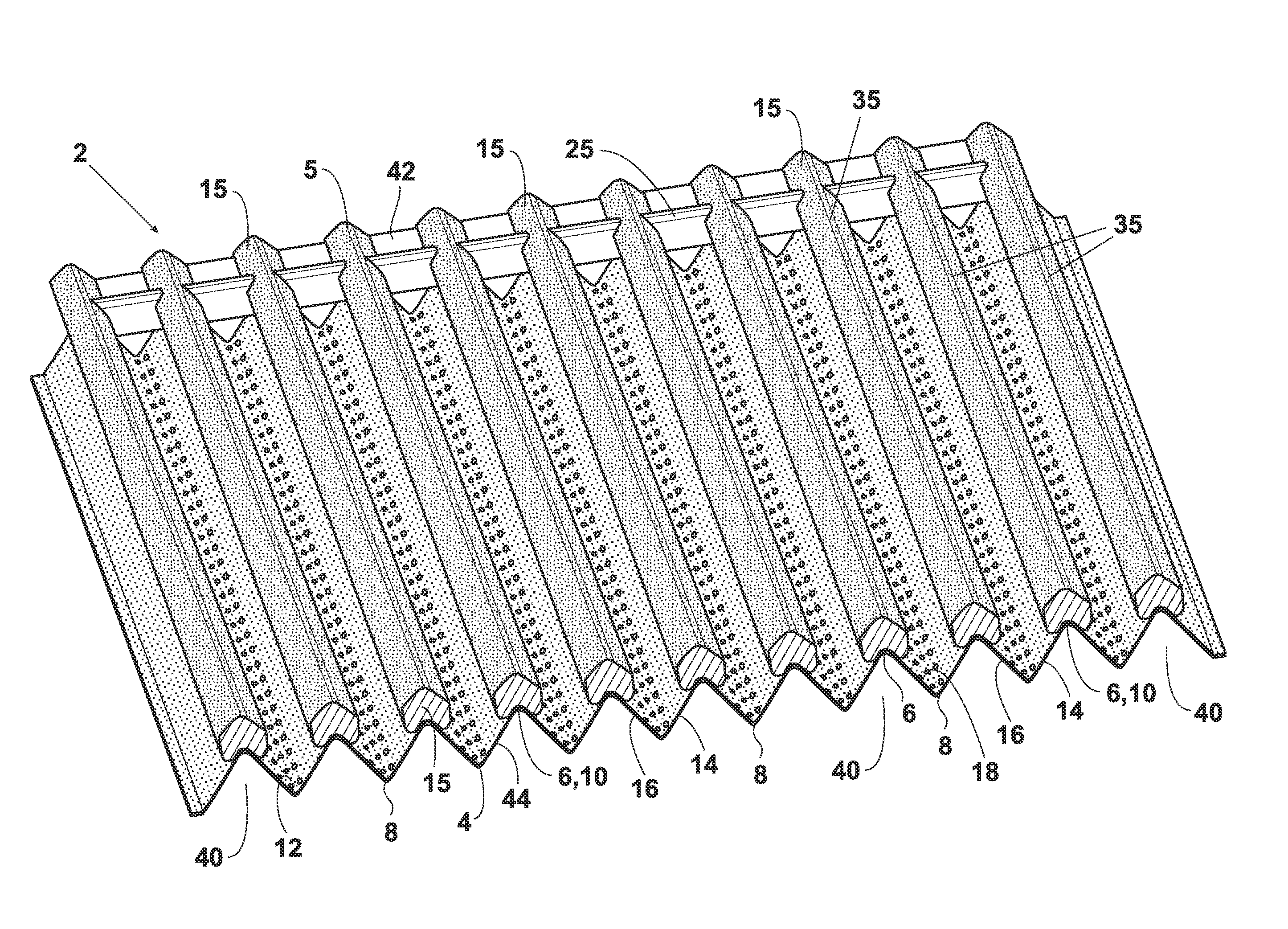
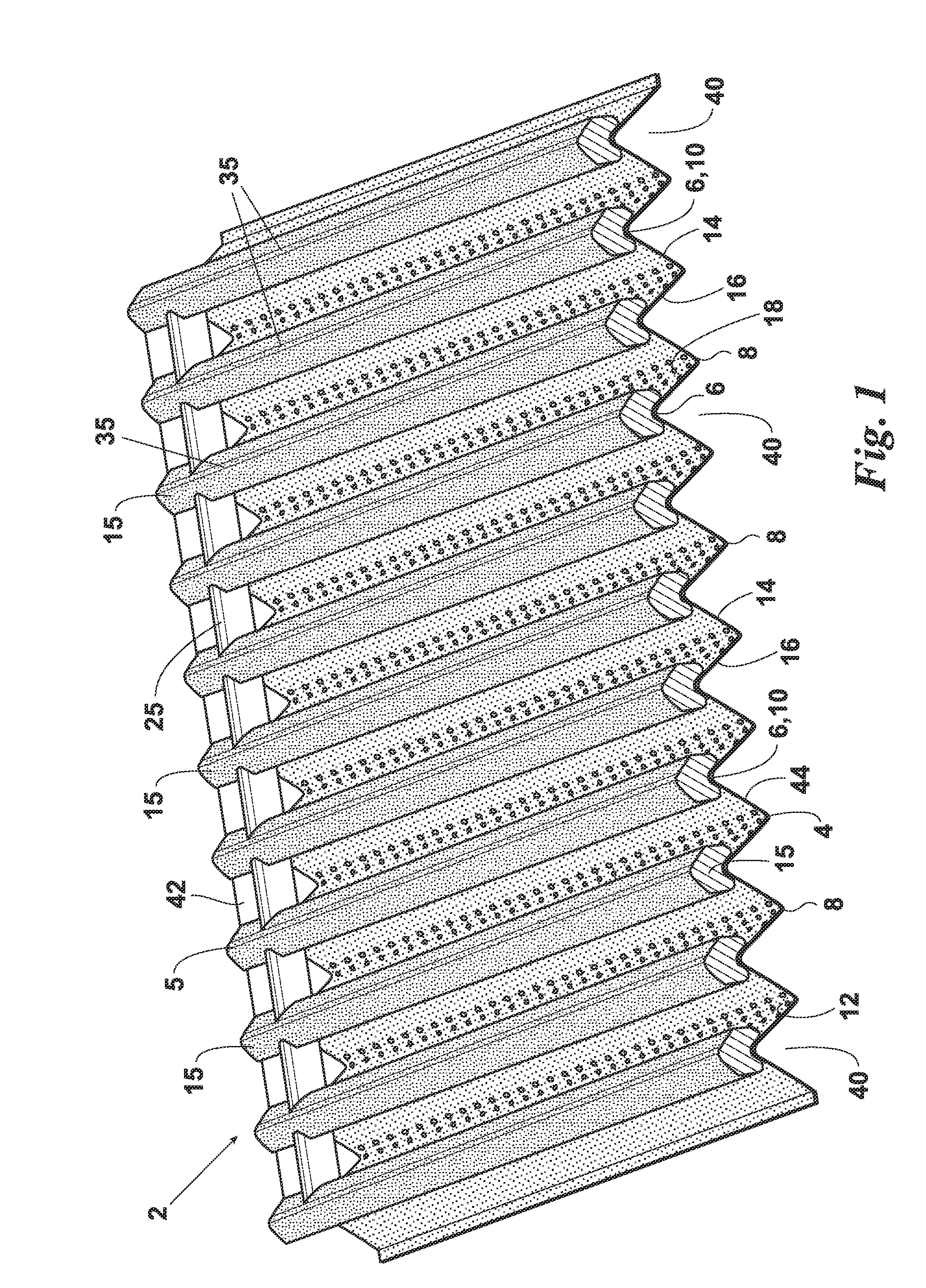
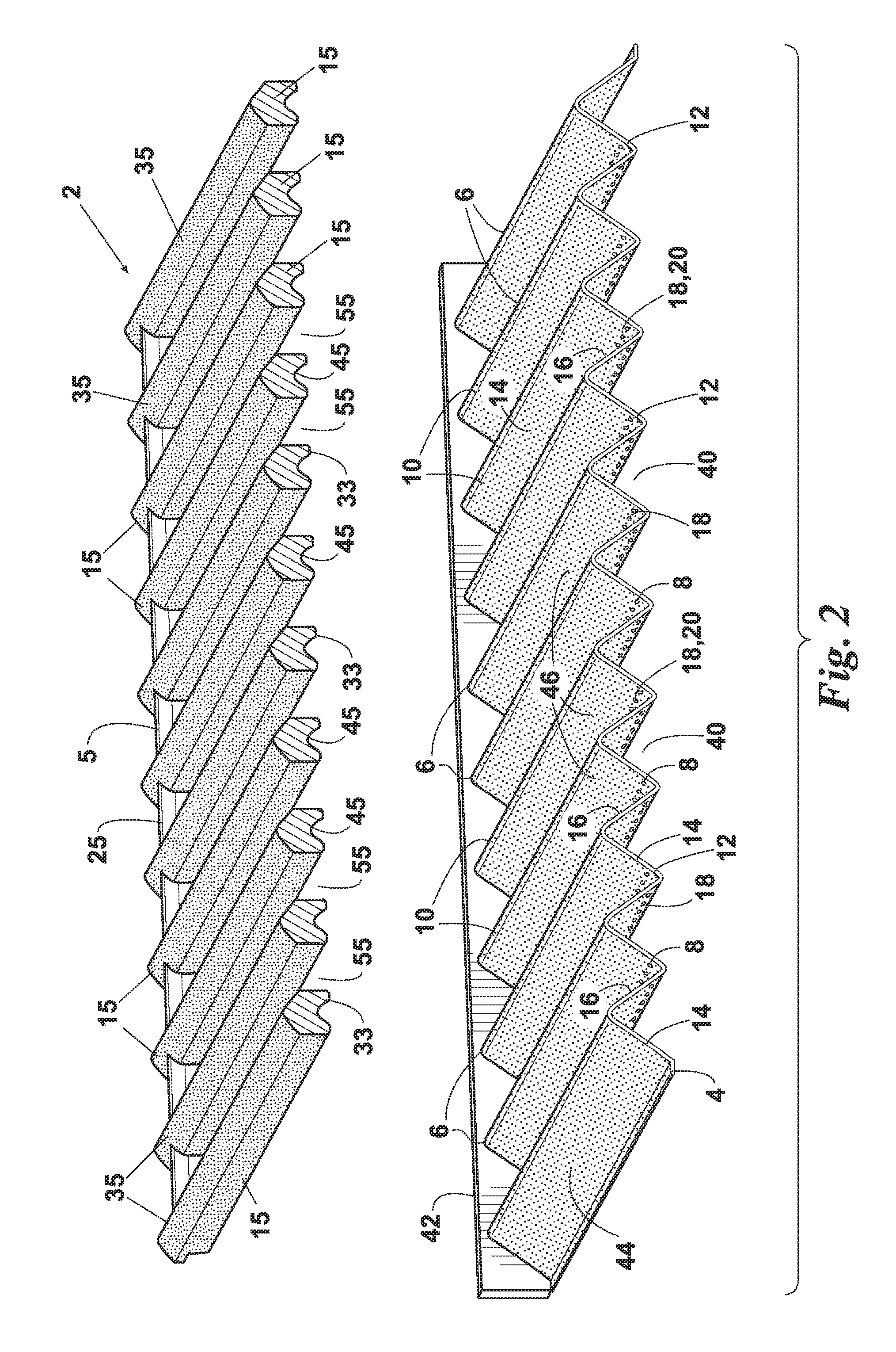
[0036]An embodiment 2 of the inventive cooking grate assembly is illustrated in FIGS. 1-3. The inventive cooking grate assembly comprises a lower grate element (preferably a lower radiating plate) 4 and an upper grate element 5 which is removably positionable on top of the lower grate element 4.

[0037]The lower grate element 4 preferably comprises a series of elongate, parallel or at least substantially parallel peak structures 6 which have elongate valleys 8 formed therebetween. The cross-sectional shapes of the peak structures 6 and valleys 8 are preferably such that: the peak structures 6 have tops 10; the valleys 8 have bottoms 12; and each peak structure 6 has a right side wall 14 and an opposing left side wall 16. In addition, the right and left side walls 14 and 16 of the peak structures 6 preferably extend from the peak tops 10 to the valley bottoms 12 such that the right and left side walls 14 and 16 of each adjacent pair of peak structures 6 also form the opposing side wall...

embodiment 4

[0040]In embodiment 4 of the lower grate element shown in FIGS. 1-3, the peak structures 6 have an inverted V cross-sectional shape such that the opposing side walls 14 and 16 of the valleys 8 are flat structures which continuously converge along straight sloping lines from the peak tops 10 to the valley bottoms 12. The slope of the side walls 14 and 16 is preferably in the range of from about 35° to about 55° from horizontal and is most preferably about 45°.

[0041]Similarly, in an alternative embodiment 100 of the lower grate element shown in FIG. 5, the side walls 114 and 116 of the valleys 108 are flat structures which converge continuously along straight sloping lines from the peak tops 110 to the valley bottoms 112. However, in the embodiment 100 of the lower grate element, the peak tops 110 are flat.

[0042]In yet another alternative embodiment 75 of the lower grate element shown in FIG. 4, the upper portions 52 of the peak structures 56 have an inverted U-shape. However, the low...


PUM


Abstract

A grate assembly for cooking food products and a grilling apparatus which uses the grate assembly for supporting the food during cooking. The grate assembly comprises: (a) a lower grate element having a series of parallel peak structures with valleys therebetween and (b) an upper grate element having a series of parallel food support ribs which are sized and spaced such that each rib will be positioned over the top of a corresponding peak structure. The upper food contacting surfaces of the ribs will remain substantially rust-free at atmospheric and cooking conditions.

Description

CROSS-REFERENCE TO RELATED APPLICATIONS[0001]This is a continuation of co-pending U.S. patent application Ser. No. 13 / 039,646, filed Mar. 3, 2011, entitled COOKING GRATE ASSEMBLY AND COOKING APPARATUS, the contents of which are hereby incorporated by reference.FIELD OF THE INVENTION[0002]The present invention relates to cooking grates and grate assemblies which support food items for cooking in outdoor grills and in other cooking systems. The invention also relates to cooking systems which utilize such grates or grate assemblies.BACKGROUND OF THE INVENTION[0003]Outdoor grilling systems which utilize infrared radiant energy for cooking food items are known in the art. The beneficial results which these systems are capable of providing over conventional convective grills are also well known. However, there are various shortcomings and deficiencies which are often associated with many current infrared systems.[0004]Even if formed of a common stainless steel or similar material, most fo...

Claims


Application Information

Patent Timeline
Patent Type & Authority Applications(United States)
IPC IPC(8): A47J37/06
CPCA47J37/0694A47J37/0682
Inventor AHMED, MALLIK
Owner W C BRADLEY CO
Learn More