
Touch detection device, display device with touch detection function, and electronic apparatus

Active Publication Date: 2014-11-27
JAPAN DISPLAY INC
View PDF20 Cites 13 Cited by
  • Summary
  • Abstract
  • Description
  • Claims
  • Application Information

AI Technical Summary

Benefits of technology

The present patent is about a device that can detect touch using a change in capacitance. It can be used in touch detection in display devices and electronic devices.

Problems solved by technology

Thus, in the touch detection device that employs a method for determining a touch point on the panel surface based on the area barycenter of such a region, there is a possibility that a difference between the determined touch point and the contact point or proximity point intended by a user occurs, thus possibly preventing improvement in the control accuracy by a user.

Method used


Image

  • Touch detection device, display device with touch detection function, and electronic apparatus
  • Touch detection device, display device with touch detection function, and electronic apparatus
  • Touch detection device, display device with touch detection function, and electronic apparatus

Examples


first embodiment

1. First Embodiment

Entire Configuration of the Display Device with a Touch Detection Function 1

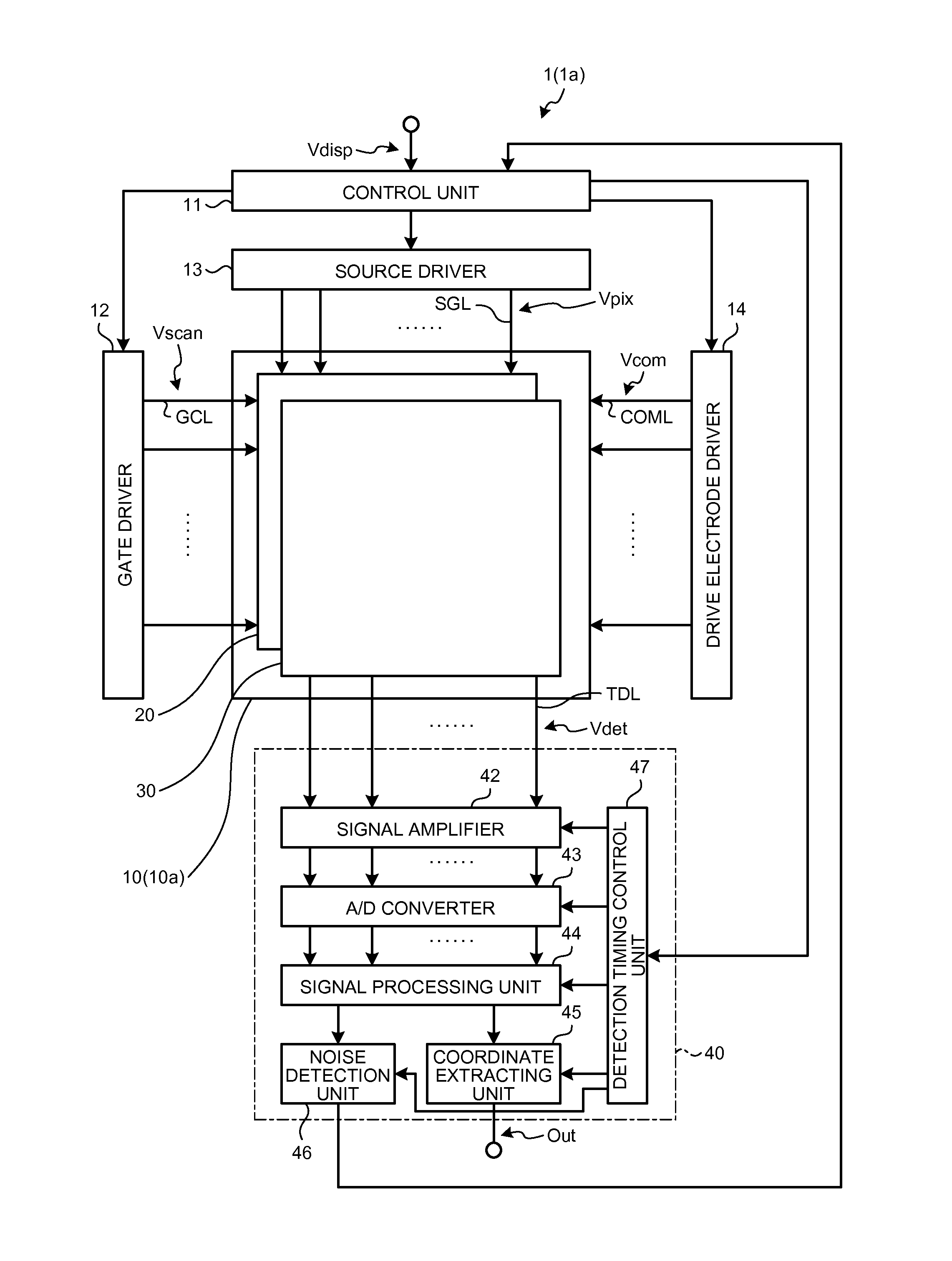
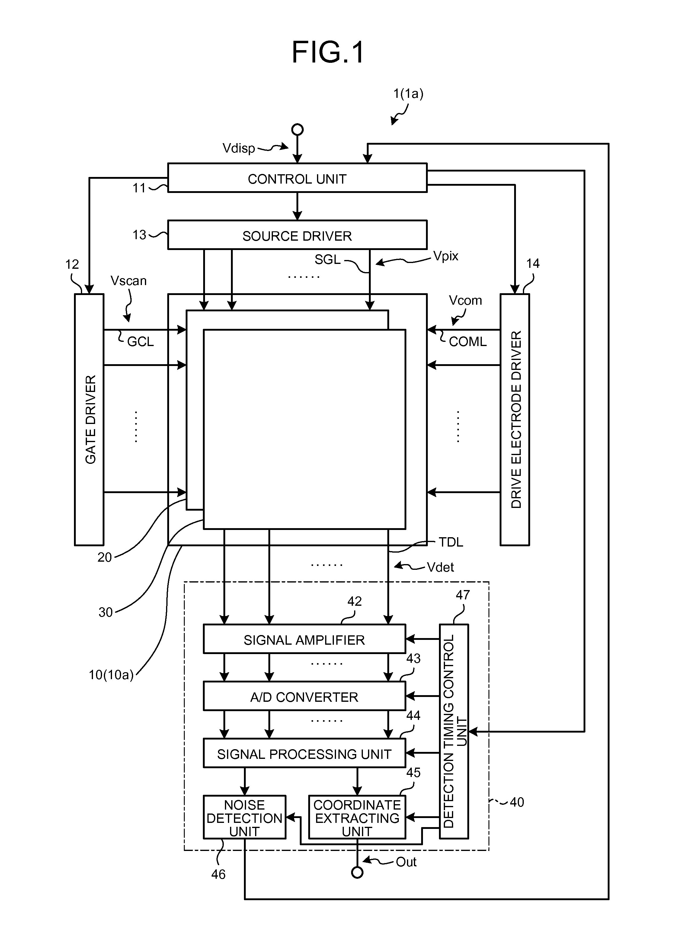
[0056]FIG. 1 is a block diagram illustrating a configuration example of a display device with a touch detection function according to a first embodiment of the present disclosure. Now, with reference to FIG. 1, a description will be made to the entire configuration of the display device with a touch detection function 1 according to the present embodiment. The display device with a touch detection function 1 illustrated in FIG. 1, which employs liquid crystal display pixels as the display pixels thereof, is a so-called in-cell type device in which a liquid crystal display unit 20 including the liquid crystal display pixels and a capacitive touch detection device 30 are integrated.

[0057]As illustrated in FIG. 1, the display device with a touch detection function 1 according to the present embodiment includes a display unit with a touch detection function 10, a control unit 11, a gate driver...

second embodiment

2. Second Embodiment

Configuration of Electronic Apparatus

[0152]FIGS. 25 to 37 are views illustrating the configuration of an electronic apparatus according to the second embodiment of the present disclosure to which a display device with a touch detection function is applied. The display device with a touch detection function 1 and the display device with a touch detection function 1a according to the first embodiment are applicable to electronic apparatuses of any field such as a television set, a digital camera, a video camera, a notebook personal computer, a mobile telephone, and a personal digital assistant. That is, the display device with a touch detection function 1 and the display device with a touch detection function 1a according to the first embodiment are applicable to electronic apparatuses of any field that display, as an image or a video, an externally supplied video signal or an internally generated video signal. Such an electronic apparatus includes a controller whi...


PUM


Abstract

According to an aspect, a display device with a touch detection function, during a touch detection operation, derives a signal value based on the touch detection signal at coordinates at which the pointer is in contact with or in proximity to the device and in the vicinity of the coordinates; derives a three-dimensional waveform which employs a magnitude of the signal value as a height direction; derives a straight line in the three-dimensional waveform, the straight line connecting between a barycenter based on a volume of a three-dimensional waveform portion equal to or greater than a first threshold value in the height direction and a barycenter based on a volume of a three-dimensional waveform portion equal to or greater than a second threshold value in the height direction; and detects based on the straight line whether the pointer is in contact with or in proximity to the device.

Description

CROSS REFERENCES TO RELATED APPLICATIONS[0001]The present application claims priority to Japanese Priority Patent Application JP 2013-111352 filed in the Japan Patent Office on May 27, 2013, the entire content of which is hereby incorporated by reference.BACKGROUND[0002]1. Technical Field[0003]The present disclosure relates to a touch detection device, a display device with a touch detection function, and an electronic apparatus which enable an external approaching object to be detected in response to a change in capacitance.[0004]2. Description of the Related Art[0005]In recent years, attention has been focused on a display device with a touch detection function which has a touch detection device or a so-called touch panel provided on a display device such as a liquid crystal display device or which has a touch detection device and a display device integrated with each other. On the display device are displayed various types of button images or the like to replace typical mechanica...

Claims


Application Information

Patent Timeline
IPC IPC(8): G06F3/044
CPCG06F3/044G06F3/0412G06F3/04166G06F3/04184G06F3/0445G06F3/0446G06F2203/04101
Inventor TANAKA, TOSHIHIKO
Owner JAPAN DISPLAY INC
Learn More