

Video display mirror and video display mirror system
a technology of video display mirror and video display mirror, which is applied in the field of video display mirror, can solve the problems of cumbersome passenger of the vehicle, deteriorating visibility of video image displayed on the monitor, etc., and achieves the effect of reducing cumbersome passenger and improving visibility of video imag
- Summary
- Abstract
- Description
- Claims
- Application Information
AI Technical Summary
Benefits of technology
Problems solved by technology
Method used
Image

Examples
first embodiment
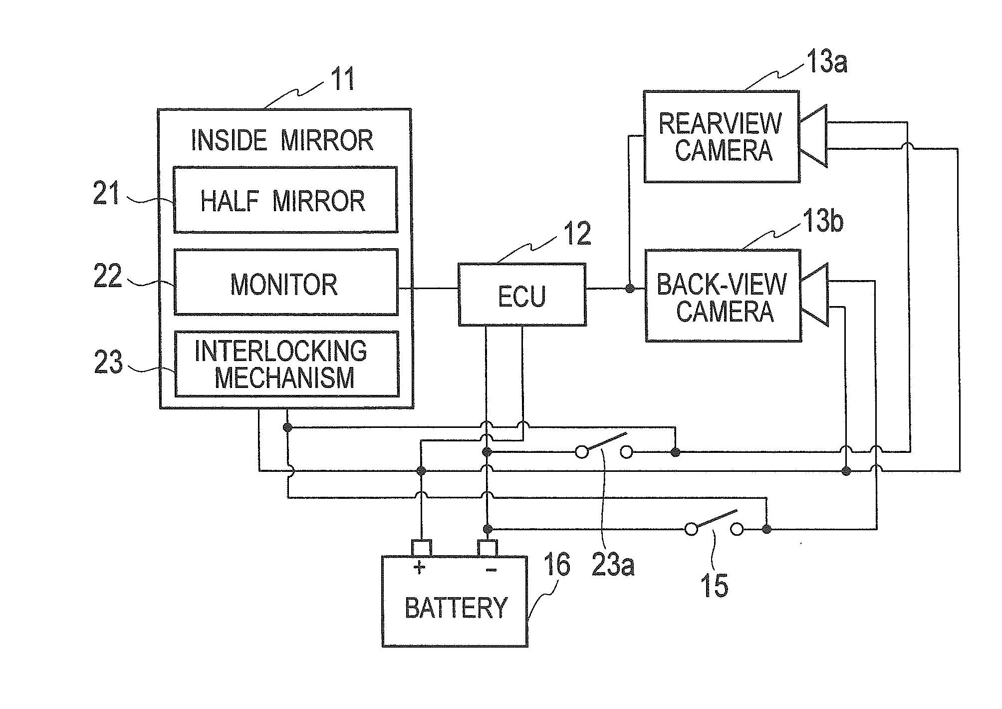
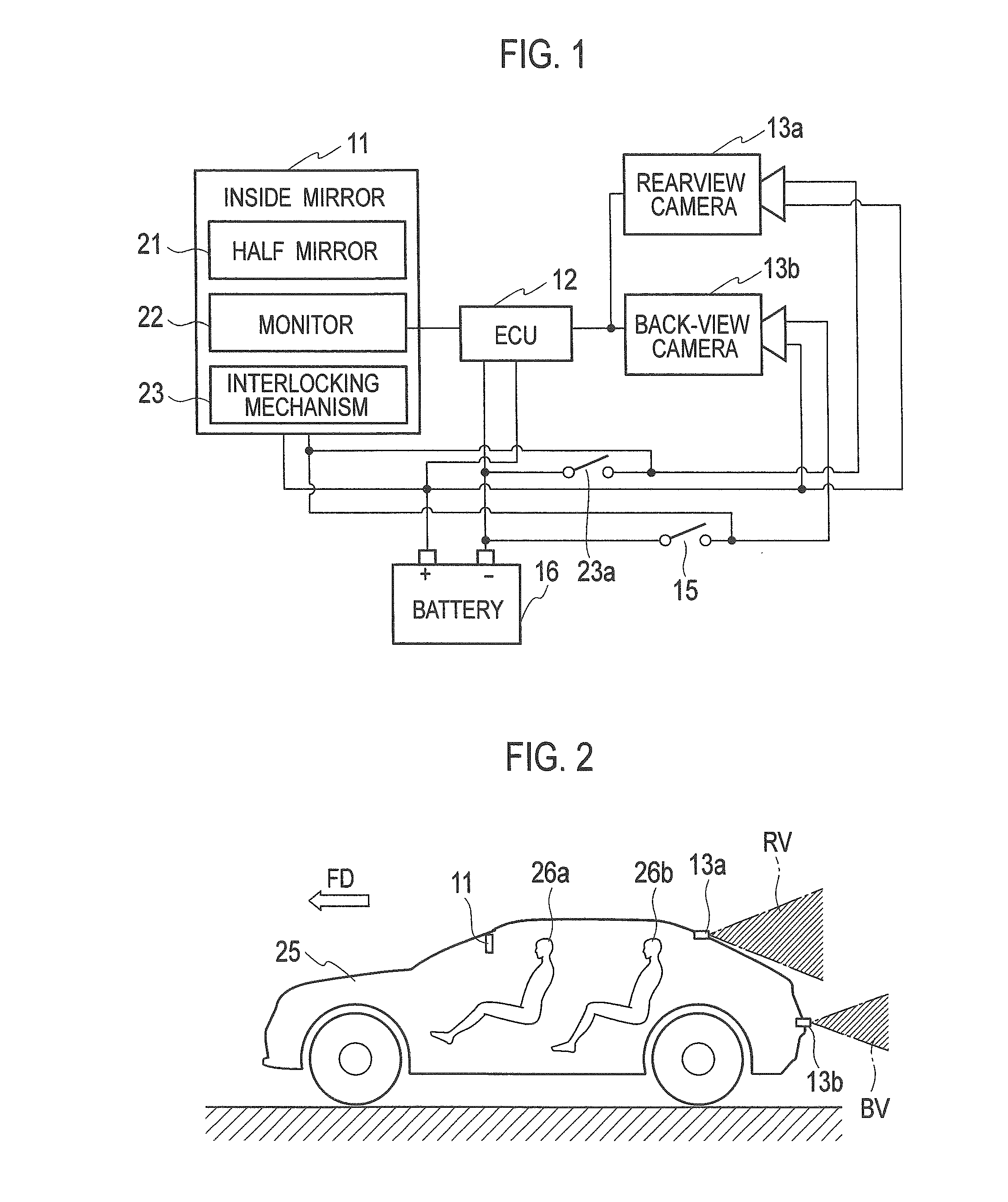
[0033]By referring to FIG. 1, configurations of a video display mirror and a video display mirror system according to a first embodiment of the present invention will be described. The video display mirror system has an inside mirror 11 provided inside a cabin, an ECU (engine control unit) 12 having a role as a video controller, cameras (13a, 13b) mounted on a vehicle and photographing a video image around the vehicle, and a battery 16 for supplying DC power to the inside mirror 11, the ECU 12, and the cameras (13a, 13b). In the embodiment, as the camera for photographing a video image around the vehicle, a rearview camera 13a for photographing a rearview for checking a following vehicle and a back-view camera 13b for imaging a back view for detecting an obstacle when the vehicle retreats will be described as an example.
[0034]To each of the inside mirror 11, the ECU 12, the rearview camera 13a, and the back-view camera 13b, wiring for supplying DC power from the battery 16 is connec...
second embodiment
[0073]In the second embodiment, instead of the manual interlocking mechanism 23, the video display mirror using an electric interlocking mechanism and the video display mirror system will be described.
[0074]By referring to FIG. 11, configurations of the video display mirror and the video display mirror system according to the second embodiment of the present invention will be described. An inside mirror 71 as an example of the video display mirror includes the electric interlocking mechanism 23. The interlocking mechanism 23 changes the angle of the reflective surface of the half mirror 21 by using a motor 72. Moreover, on an instrument panel of the vehicle 25, a switching switch 23c is provided at a position where the passenger 26a can perform an operation. As illustrated in FIG. 11, both terminals of the switching switch 23c are directly connected to the ECU 12, and the ECU 12 receives a signal indicating a state of the switching switch 23c. The ECU 12 receives the reverse signal ...
third embodiment
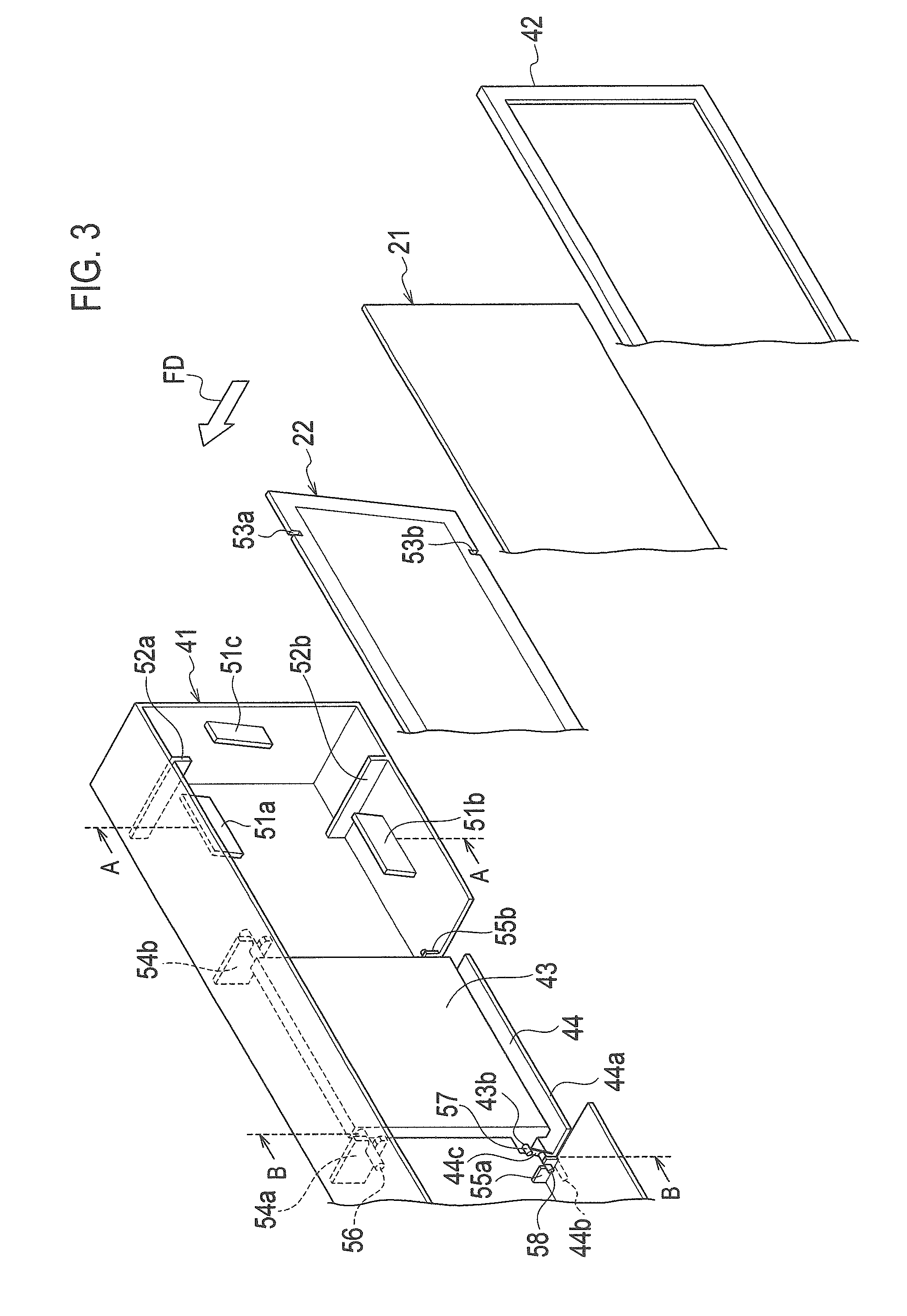
[0098]In the first and second embodiments, the inside mirror 11 in which the bracket 43 is fixed to the front window of the vehicle 25, and the interlocking mechanism 23 changes the angles of the housing 41, the half mirror 21, and the monitor 22 with respect to the bracket 43 is described.
[0099]On the other hand, in a third embodiment, the inside mirror 11 in which the half mirror 21 and the monitor 22 are fixed to a bracket 83, the housing 41 is fixed to the front window of the vehicle 25, and the interlocking mechanism 23 changes the angles of the bracket 83, the half mirror 21, and the monitor 22 with respect to the housing 41 will be described.
[0100]The configuration of the video display mirror system illustrated in FIG. 1, the mounted example of the video display mirror system on the vehicle illustrated in FIG. 2, and the operation example of the video display mirror system illustrated in FIG. 9 are the same as those in the first embodiment, and the explanation will be omitted...
PUM
 Abstract
Description
Claims
Application Information