Method of widening of angular field of view of collimating optical systems

Inactive Publication Date: 2014-11-27
LVOVSKIY MATVEY +1
View PDF2 Cites 6 Cited by
  • Summary
  • Abstract
  • Description
  • Claims
  • Application Information

AI Technical Summary

Benefits of technology

This patent is about improving image quality in collimating optical systems, like displays, by using a primary image creator and unified optical systems. This helps to effectively use the wider information field and enhance image quality within the field of view.

Problems solved by technology

There are challenges (irresistible in some cases) if large-dimension optical elements and systems are used under the restricted space conditions such as aircraft, piloted spaceship or specific surface transportation.
Further increase of diameter of the exit lens is undesirable since it causes increase of size and weight of display that could affect flight safety.
In such collimating optical systems single or several HOE installed at the exit of optical system and at the same time in front of the pilot are most sophisticated and bulky optical components.
In order to make such HOE complicated manufacturing technology is required that have to meet conditions of high vibration resistance and seismic stability and it is labor-intensive and costly and accessible only for advanced manufacturers.
It is practically impossible to use image creators based on color LCD, e.g., and accordingly to represent color information picture.

Method used


Image

  • Method of widening of angular field of view of collimating optical systems
  • Method of widening of angular field of view of collimating optical systems
  • Method of widening of angular field of view of collimating optical systems

Examples


Embodiment Construction

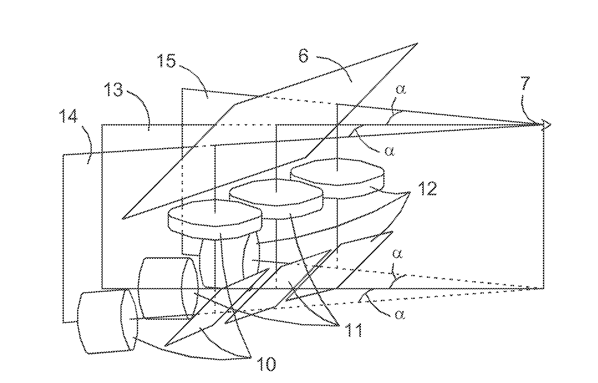
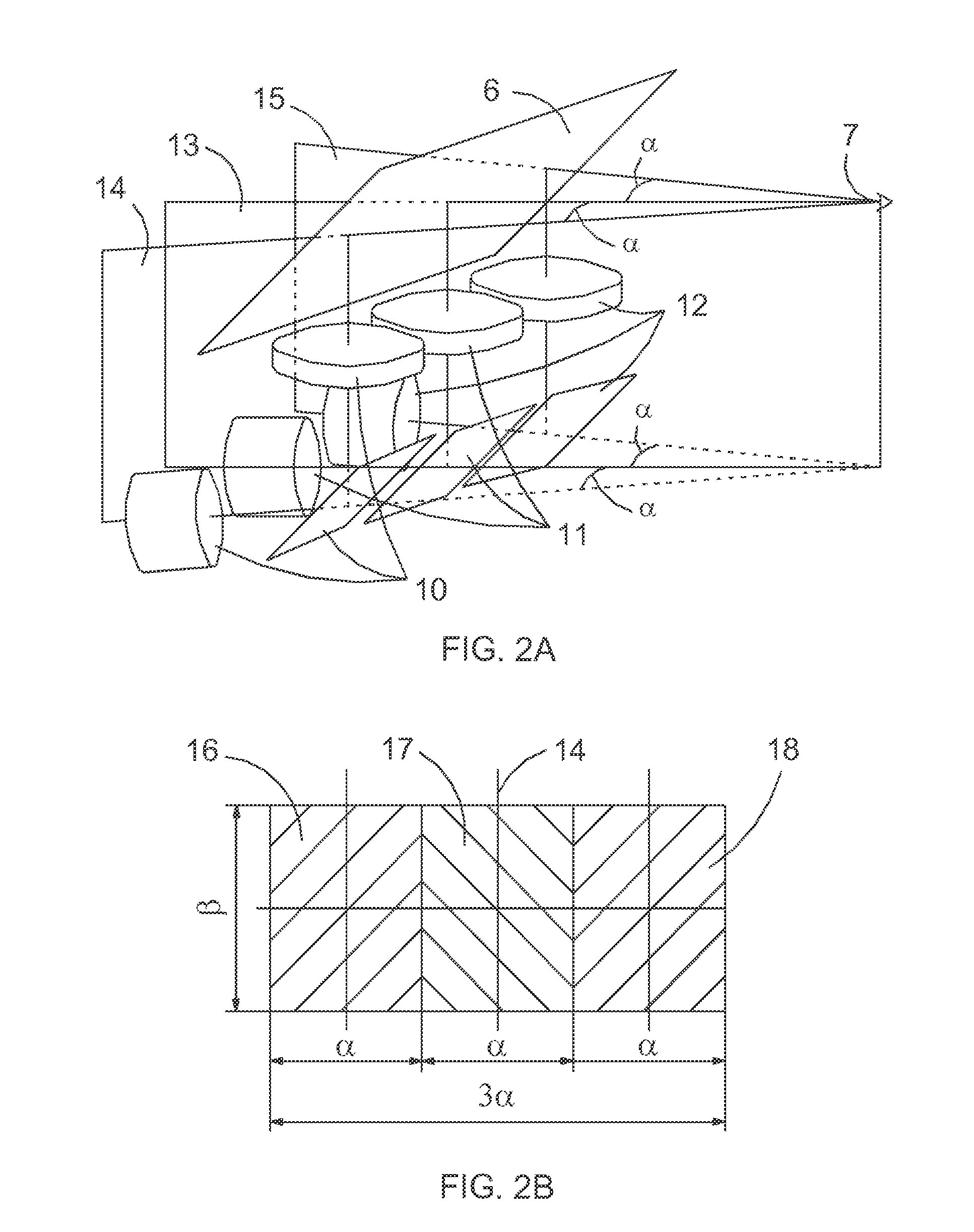
[0032]By the method suggested the collimating optical system contains several unified optical systems spaced out horizontally with angular fields of view of rectangular shape boundaries of that are oriented horizontally and vertically. Vertical symmetry planes of unified optical systems are turned horizontally in such way that adjacent vertical boundaries of neighboring systems are superposed and full angular field of view of collimating optical system is equal to the sum of angular fields of view of unified optical systems included in the system.

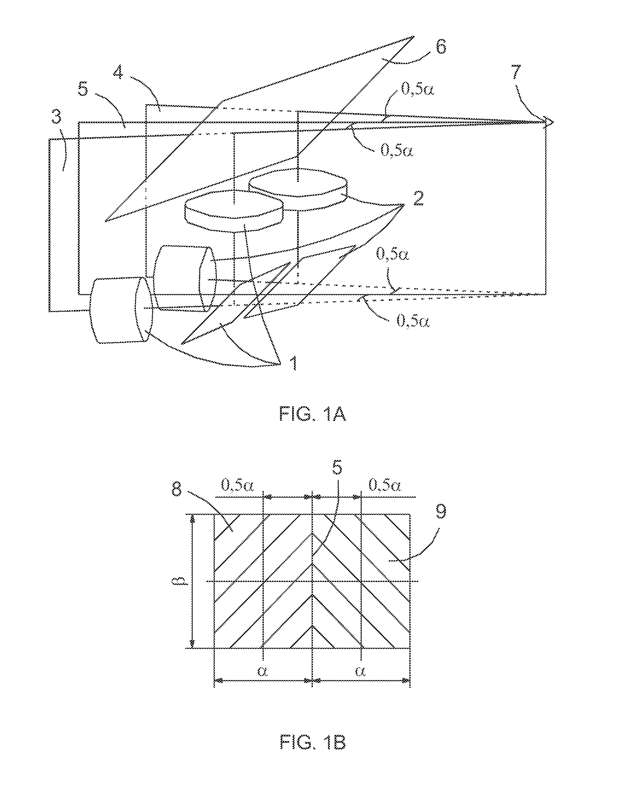
[0033]FIG. 1A shows architecture layout of one of feasible variants of collimating optical system built according to suggested method. It contains two unified optical systems 1 and 2 spaced out horizontally with equal fields of view of rectangular shape the boundaries of that are oriented horizontally and vertically. Vertical symmetry plane 3 of the left unified optical system (1) and vertical symmetry plane 4 of the right unified optical s...


PUM


Abstract

Method of horizontal widening of angular field of view of collimating optical system using several unified ax symmetric collimating optical systems spaced out horizontally with angular fields of view of rectangular shape with their boundaries oriented horizontally and vertically and their axes are turned horizontally relative to each other so that adjacent vertical boundaries of angular fields of view of neighboring systems coincide and full angular field of view of collimating optical system is sum of angular fields of view of unified optical systems included in it and to display total virtual information collimating optical system is conjugated with two-component combiner and primary image creators e.g. LCDs are located in focal planes of unified optical systems and wide-angle panoramic collimating optical system with horizontal field of view up to 360° can be build also.

Description

BACKGROUND OF THE INVENTION[0001]Suggested method of widening of angular field of view of collimating optical systems used in equipment of various type differs from known methods. The best known and widely applied methods of design of such optical systems are stated below.[0002]Routine method is based on application of ax symmetric collimating optical systems with spherical optical elements and widening of angular field of view accessible for perception by operator is attained by increase of aperture of optical system at the expense of appropriate increase of size (diameters) of optical elements (lenses, mirrors, prisms, etc.). Usually the size of optical system is not crucial if it is used under steady-state conditions. There are challenges (irresistible in some cases) if large-dimension optical elements and systems are used under the restricted space conditions such as aircraft, piloted spaceship or specific surface transportation. Therefore following analysis of various methods o...

Claims


Application Information

Patent Timeline
IPC IPC(8): G02B27/30
CPCG02B27/30G02B27/0101G02B2027/0123G02B2027/0118G02B27/01G02B27/0172
Inventor LVOVSKIY, MATVEYEFROS, ALEXSANDER
Owner LVOVSKIY MATVEY
Why Eureka
Try Eureka