
Modular and Reconfigurable Support System

a support system and modular technology, applied in the field of modular and reconfigurable support systems, can solve the problems of limiting the access of personnel and/or equipment to the wing skin and/or the wing box, difficulty for operators, and the current available system for supporting and loading the wing skin may be less ergonomic than desired

Active Publication Date: 2014-12-04
THE BOEING CO
View PDF0 Cites 50 Cited by
  • Summary
  • Abstract
  • Description
  • Claims
  • Application Information

AI Technical Summary

Benefits of technology

The patent describes an apparatus and method for supporting and loading objects in a flexible manufacturing environment. The apparatus includes a support structure, positioning system, retention system, and attachment system. The support structure can be positioned with respect to a platform using the positioning system. The retention system can hold a portion of an object and move it towards the platform until it conforms to the shape of the platform. The attachment system can attach a tool to the support structure. The method can be used to support and load wing skins underneath wing boxes in a flexible manufacturing environment. The apparatus and method allow for efficient and flexible support and loading of objects in various shapes and sizes.

Problems solved by technology

Some currently available systems for supporting and loading a wing skin to the lower side of a wing box may create obstacles that limit access to the wing skin and / or wing box by personnel and / or equipment.
For example, without limitation, the obstacles presented by this type of support system may present challenges for an operator to access certain portions of the wing skin and / or wing box without running into the support system and / or other equipment.
Further, some currently available systems for supporting and loading a wing skin may be less ergonomic than desired.
Consequently, performing operations, such as drilling operations, fastening operations, tacking operations, and / or other operations, may be more difficult and / or time-consuming than desired with these types of support systems.
The system requirements and complexity of the automated tools that may be used with these types of currently available systems may be greater than desired.
Additionally, some currently available support systems may not be reconfigurable.
In other words, a support system used for loading wing skins for one type of aircraft may be unable to load wing skins for a different type of aircraft.
Further, these types of support systems may require dedicated tooling, which may increase the cost of using these types of support systems more than desired.
Altering a support system to accommodate different types of aircraft and / or different types of geometry may be more difficult than desired and, in some cases, not possible.
Additionally, some support systems may not integrate lifting the wing skins with the handling of the wing systems.
Using this type of numerically-controlled lift system may be more expensive than desired and may obstruct access to portions of the wing skin and / or the wing box more than desired.

Method used


Image

  • Modular and Reconfigurable Support System
  • Modular and Reconfigurable Support System
  • Modular and Reconfigurable Support System

Examples


Embodiment Construction

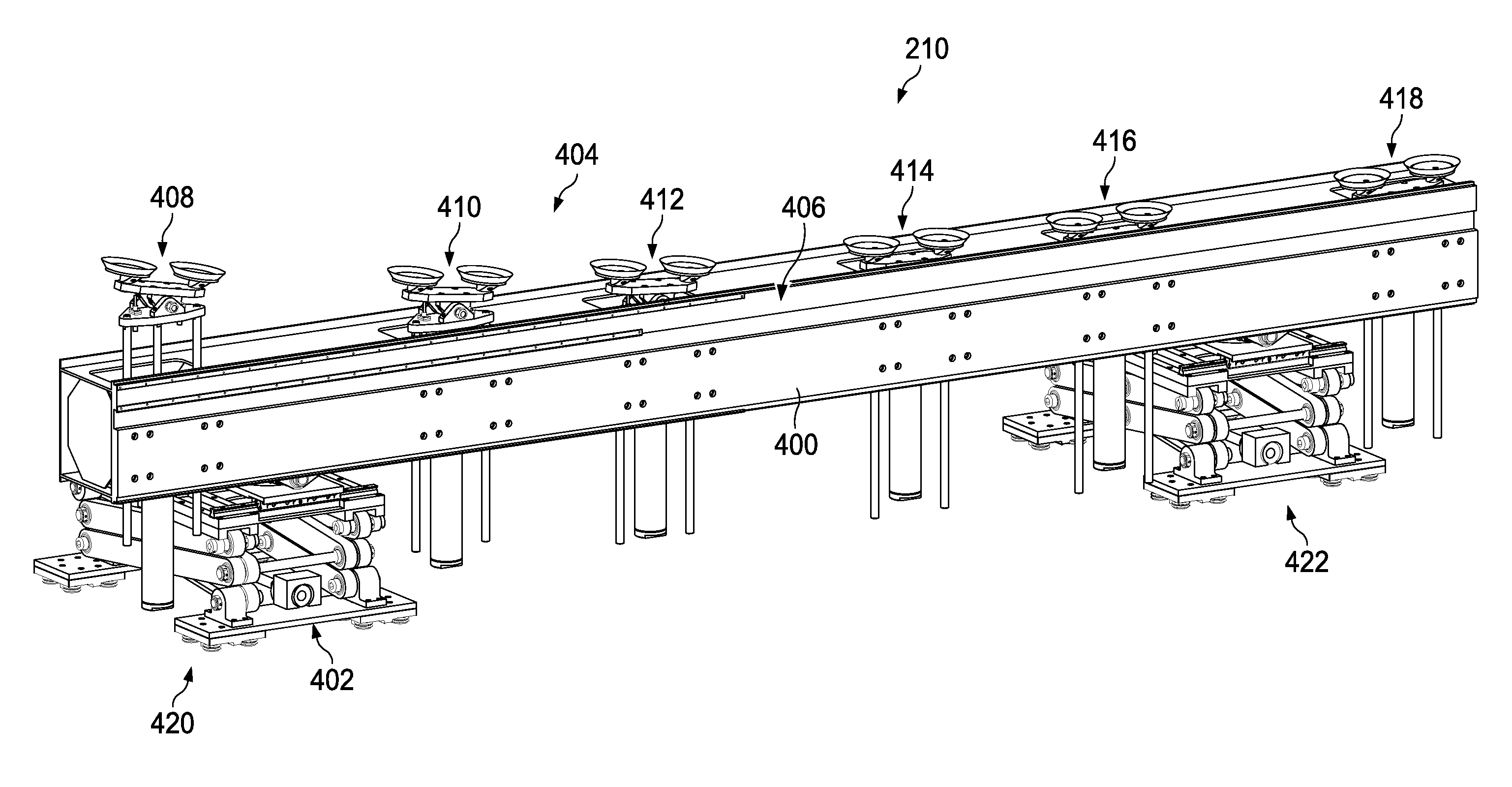
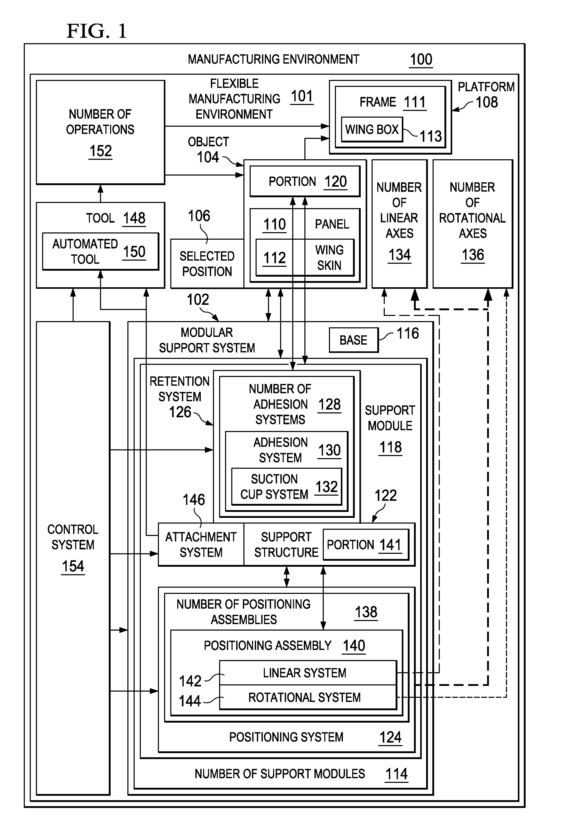
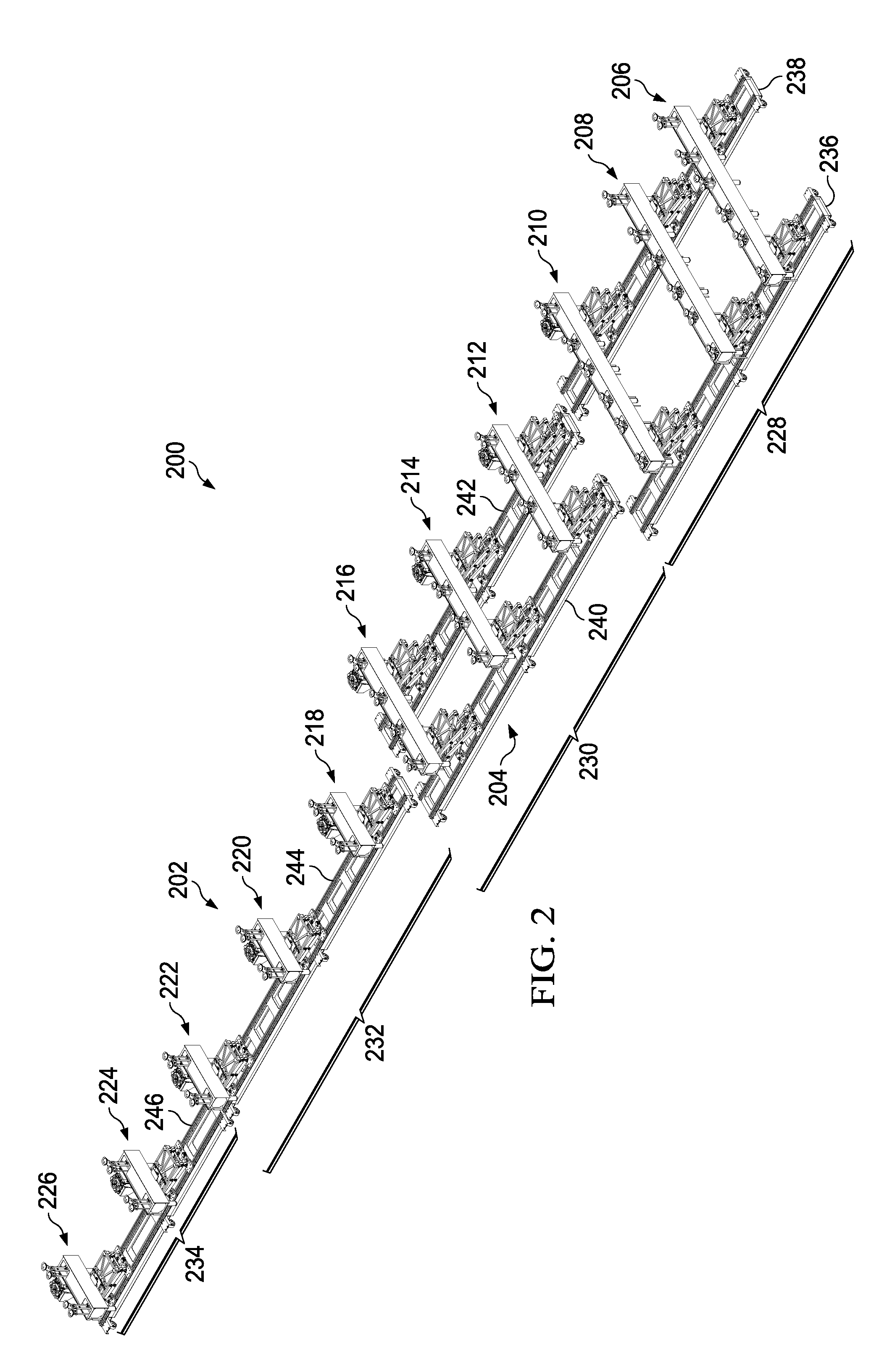
[0043]The illustrative embodiments recognize and take into account different considerations. For example, the illustrative embodiments recognize and take into account that it may be desirable to have a reconfigurable support system capable of supporting and loading a wing skin underneath a wing box for an aircraft. Further, the illustrative embodiments recognize and take into account that it may be desirable to have a support system that does not create obstacles for personnel and / or equipment attempting to perform operations on the wing skin and / or the wing box.

[0044]Thus, the illustrative embodiments provide an apparatus, system, and method for supporting and loading a wing skin underneath a wing box. In particular, the illustrative embodiments provide a modular support system that may be reconfigured for different types of aircraft. Further, this modular support system may allow for operations to be performed without creating obstacles for the personnel and / or equipment needed to...


PUM

PropertyMeasurementUnit
shapeaaaaaaaaaa
adhesionaaaaaaaaaa
pressureaaaaaaaaaa

Abstract

An apparatus and method for supporting an object. In one illustrative embodiment, an apparatus may comprise a support structure, a positioning system, and a retention system. The positioning system may be associated with the support structure and configured to position the support structure with respect to a number of linear axes. The retention system may be associated with the support structure. The retention system may be configured to retain a portion of an object and move the portion of the object towards a platform such that the portion of the object substantially conforms to a shape of the platform.

Description

BACKGROUND INFORMATION[0001]1. Field[0002]The present disclosure relates generally to installing panels on structures and, in particular, to attaching a wing skin to a wing box. Still more particularly, the present disclosure relates to a modular and reconfigurable support system for use in supporting, positioning, and loading a wing skin underneath a wing box for attachment to the wing box.[0003]2. Background[0004]The wing of an aircraft may be formed using a wing box and two wing skins. One wing skin may be attached to the upper side of the wing box, while the other wing skin may be attached to the lower side of the wing box. Depending on the implementation, a wing skin may be attached to a support structure of the wing box, ribs, spars, stringers, and / or one or more other types of components used to form a wing. Some currently available systems for supporting and loading a wing skin to the lower side of a wing box may create obstacles that limit access to the wing skin and / or win...

Claims


Application Information

Patent Timeline
Patent Type & Authority Applications(United States)
IPC IPC(8): B23Q1/64B23Q1/25
CPCB23Q1/25B23Q1/64B23P19/10B23P2700/01B64F5/10Y10T29/49998B23Q1/035B23Q1/037
Inventor DESJARDIEN, MATTHEW R.REID, ERIC M.BUTTRICK, JAMES N.JONES, DARRELL DARWINDAY, DAN DRESSKELLSTONE, PAUL REED
Owner THE BOEING CO
Features
  • Generate Ideas
  • Intellectual Property
  • Life Sciences
  • Materials
  • Tech Scout
  • Unparalleled Data Quality
  • Higher Quality Content
  • 60% Fewer Hallucinations
Learn More