Sealing arrangment and method for the production thereof

a technology of sealing arrangment and sealing ring, which is applied in the direction of engine seals, engine components, mechanical apparatuses, etc., can solve the problems of little advantage in technical production-related aspects and unsatisfactory sealing action during use, and achieve the effects of effective protection from contamination, reduced mechanical load, and less flexibility

Inactive Publication Date: 2014-12-04
TRELLEBORG SEALING SOLUTIONS GERMANY
View PDF16 Cites 6 Cited by
  • Summary
  • Abstract
  • Description
  • Claims
  • Application Information

AI Technical Summary

Benefits of technology

[0007]The advantage connected with the seal arrangement according to the invention substantially involves an improved sealing function of the sealing lip. The free end portion of the sealing lip is supported in a resilient manner by means of the pretensioning element on one machine component and is pressed by the pretensioning element with a defined, that is to say, freely predeterminable, contact pressure against the other machine element, that is to say, the sealing face thereof. Consequently, even during use in highly contaminated environments, there is a clearly reduced introduction of contamination, such as, for example, particles of dirt, and / or an operating fluid in the region of the sliding guide. Furthermore, a discharge of lubricant which is arranged in the region of the sliding guide, that is to say, in the sealing gap which is intended to be sealed between the two machine components, for example, lubricating oil, is counter-acted in a more reliable manner. This applies to translatory and / or rotary movements of the two machine components with respect to each other. On the whole, the required maintenance intervals of the seal arrangement can thereby be extended and the service-lives of the seal arrangement can be increased as a whole. Furthermore, with the seal arrangement according to the invention, additional sealing and / or wiping elements to protect the sliding guide formed by the seal, in particular from abrasive particles of dirt or the like, are required only in exceptional cases or are completely superfluous. This enables a structurally more simple and more compact structure of the seal arrangement. This on the whole affords economic advantages.
[0008]The seal is retained on one machine component with radial and / or axial press-fitting and may be constructed as an inner or an outer seal. In the case of an inner seal, the seal is surrounded in an at least partially peripheral manner by one machine component which is constructed, for example, as a cylinder. If the seal is constructed as an outer seal, it surrounds one machine component, for example, a piston, at the peripheral side. This embodiment is preferred in the case of high demands in terms of the transverse stability of the seal and the sliding guide which is formed thereby. On the whole, a particularly good range of uses of the seal arrangement is thereby enabled.
[0009]According to a preferred development of the invention, the seal covers the seal retention structure in a radial direction and is preferably in direct abutment therewith. The sliding guide for both machine components can thereby be constructed in this region in a simple manner so as to be rigid, that is to say, non-flexible in a radial direction. This enables precise guiding or support of the two machine components relative to each other.

Problems solved by technology

Such a seal arrangement, as known, for example, from DE 195 13 727 A1, often has only an unsatisfactory sealing action during use.
This is costly and has little advantage in terms of technical production-related aspects.

Method used


Image

  • Sealing arrangment and method for the production thereof
  • Sealing arrangment and method for the production thereof
  • Sealing arrangment and method for the production thereof

Examples


Embodiment Construction

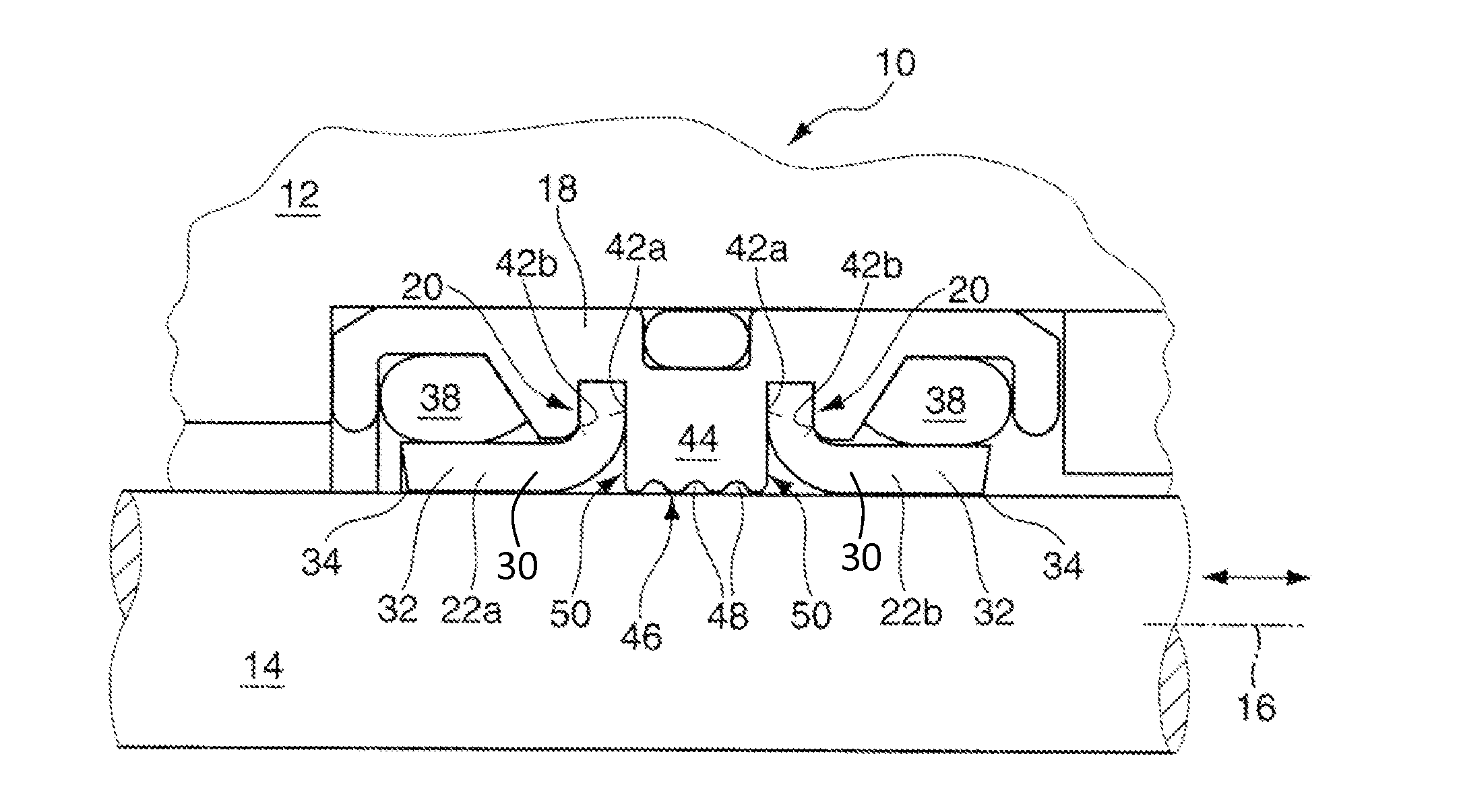
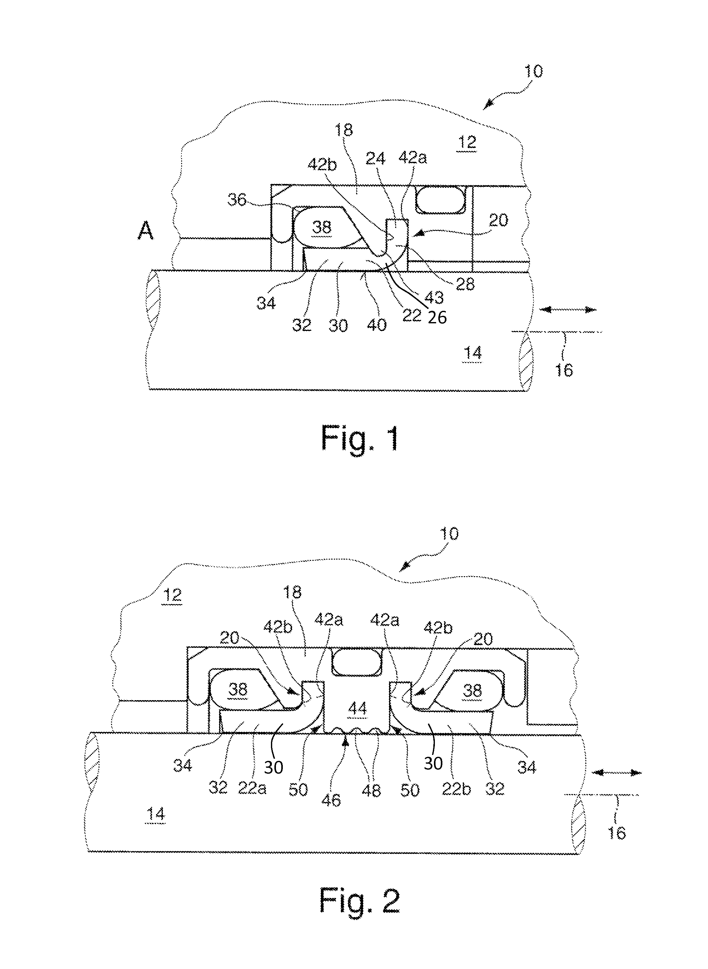
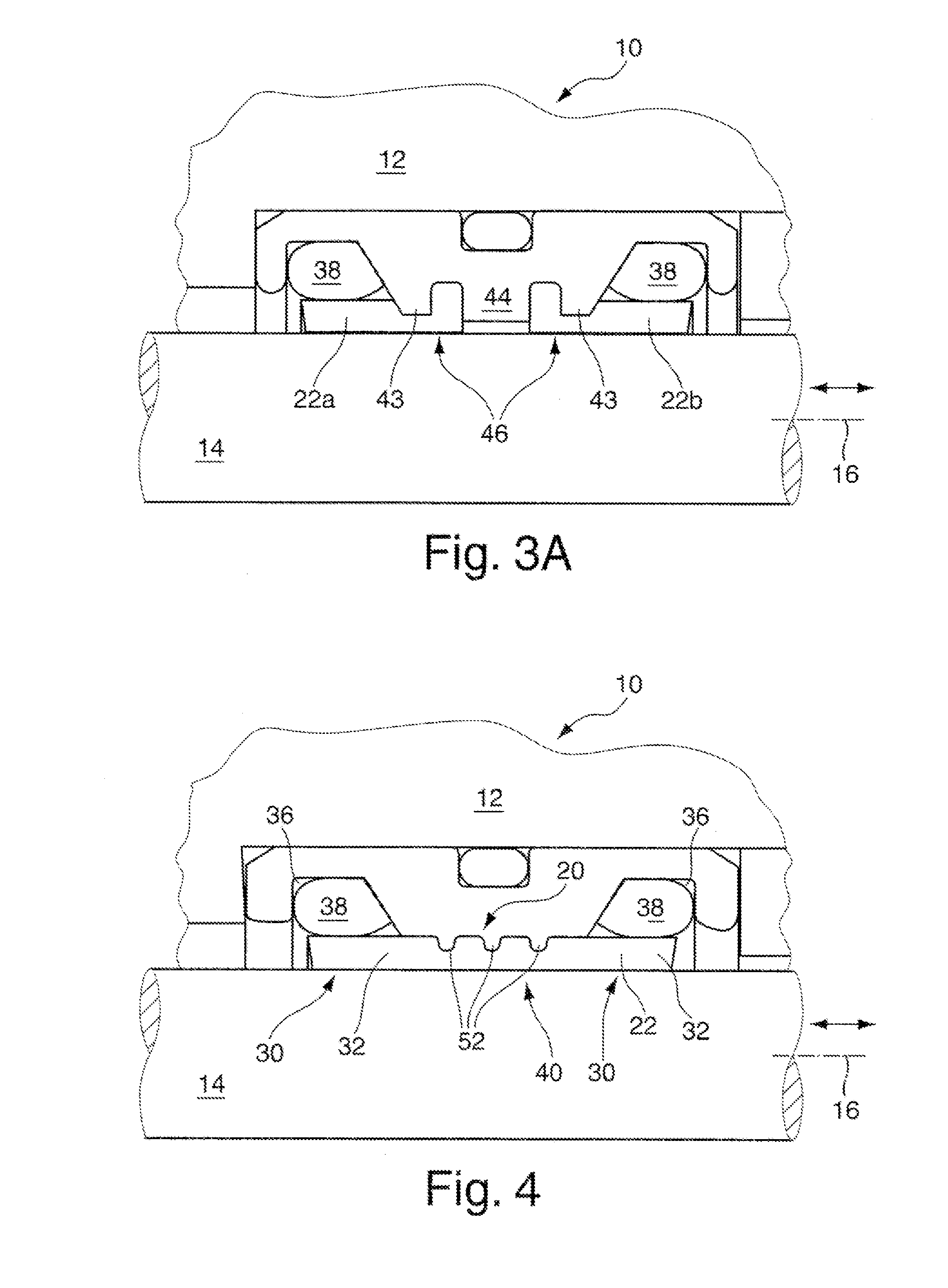
[0037]FIG. 1 shows a seal arrangement 10 having two machine components 12, 14 which are arranged so as to be able to be moved relative to each other along a movement axis 16. The machine component 12 is in this instance constructed by way of example as a cylinder and the machine component 14 is constructed as a piston which is arranged so as to be able to be moved back and forth in the cylinder. The machine component 12 has a cartridge-like seal insert 18 of a substantially rigid, in this instance metal, material. The seal insert 18 has a seal retention structure 20 which is constructed as a retention groove and in which a seal 22 is retained with axial press-fitting with a terminal securing portion 24. The securing portion 24 is connected by means of a bent seal portion 26 to a sealing lip 30 which extends longitudinally in an axial direction 28. The sealing lip 30 extends away from the seal retention structure 20 of the machine component 12 in an axial direction and protrudes in a...


PUM


Abstract

A seal arrangement includes two machine components which are arranged so as to be able to be moved relative to each other along / about a movement axis, and having at least one resiliently deformable seal which is retained in a press-fitting manner on a seal retention structure on one of the two machine components. The seal forms a sliding guide for the two machine components, and has at least one sealing lip which is in sealing abutment with the other machine component in each case and which extends in an axial direction away from the seal retention structure. A free end portion of the sealing lip is supported by means of at least one resiliently deformable pretensioning element on one machine component in such a manner that the free end portion is in abutment with the other machine component with a defined contact pressure.

Description

CROSS-REFERENCE TO RELATED APPLICATIONS[0001]This continuation application claims priority to PCT / EP2013 / 052850 filed on Feb. 13, 2013 which has published as WO 2013 / 124192 A1 and also the German application number 10 2012 202 571.5 filed on Feb. 20, 2012, the contents of which are fully incorporated herein with these references.DESCRIPTION[0002]1. Field of the Invention[0003]The invention relates to a seal arrangement having two machine components which are arranged so as to be able to be moved relative to each other along and / or about a movement axis, and having at least one resiliently deformable seal which is retained in a press-fitting manner on a seal retention structure on one of the two machine components, the seal forming a sliding guide for the two machine components. The seal has at least one sealing lip which is in sealing abutment with the other machine component in each case and which extends in an axial direction away from the seal retention structure.BACKGROUND OF TH...

Claims


Application Information

Patent Timeline
Patent Type & Authority Applications(United States)
IPC IPC(8): F16J15/32
CPCF16J15/3204F16J15/3208F16J15/3228F16J15/56
Inventor JORDAN, HOLGER
Owner TRELLEBORG SEALING SOLUTIONS GERMANY
Why Eureka
Try Eureka