Image forming apparatus

Active Publication Date: 2014-12-04
SHARP KK
View PDF8 Cites 9 Cited by
  • Summary
  • Abstract
  • Description
  • Claims
  • Application Information

AI Technical Summary

Benefits of technology

[0023]When there is a potential difference between the surface of the pressure rotation member and toner, a first cleaning mechanism is preferably provided to clean the surface of the pressure rotation member. Instead of the first cleaning mechanism, a second cleaning mechanism may be provided so as to clean the surface of the fixing rotation member. Both of the first cleaning mechanism to clean the surface of the pressure rotation member and the second cleaning mechanism to clean the surface of the fixing rotation member may be provided. This al

Problems solved by technology

The electrophotographic printing, however, has a concern about the surrounding of the transfer portion getting dirty due to toner sticking out from a sheet or flying off from the end part of a sheet because the toner used as a developer is powder, and so has not used margin-less printing positively.
Especially when the sheet guide becomes dirty with toner, the toner will be attached to a sheet passing through the sheet guide during the following usual margin printing, and so the printing quality will be degraded unfortunately.
The method of Japanese Unexamined Patent Application Publication No. 2009-86140 requires a shee

Method used


Image

  • Image forming apparatus
  • Image forming apparatus
  • Image forming apparatus

Examples


embodiment 1

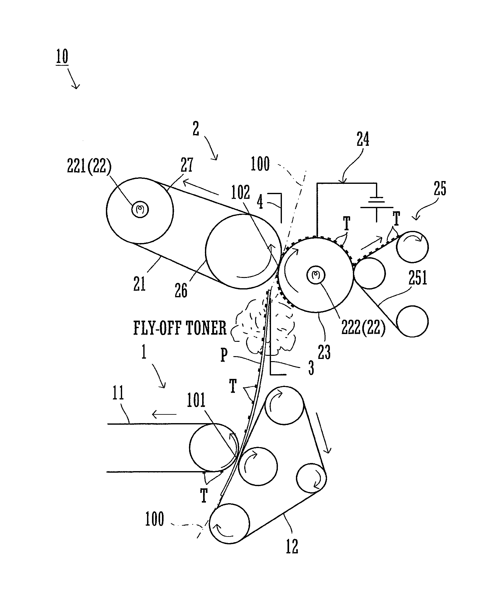
[0033]The following describes embodiments of the present invention, with reference to the drawings. FIG. 1 illustrates major parts of an image forming apparatus 10 of the present invention. Since other configuration making up the image forming apparatus 10, which is not illustrated in the drawing, is known, illustration and descriptions thereof are omitted. The image forming apparatus 10 of the present invention supports margin-less printing to enlarge a printing region to at least one end part of a sheet in the width direction that is orthogonal to the sheet conveyance direction.

[0034]As illustrated in FIG. 1, the image forming apparatus 10 includes a transfer portion 101 and a fixing portion 102 that are disposed along a sheet conveyance path 100 to convey a sheet P.

[0035]At the transfer portion 101, a transfer device 1 transfers a toner image on a sheet P. In this drawing, letter T indicates toner (powder) to make up a toner image.

[0036]The transfer device may be any type. In th...

embodiment 3

[0061]Referring to FIG. 6, the following describes The present embodiment is configured so that a web 251 of a cleaning mechanism 25 comes into contact with a secondary transfer belt 12 as well, whereby a pressure roller 23 and the secondary transfer belt 12 can be cleaned by a common cleaning mechanism 25.

[0062]Referring to FIG. 7, the following describes Embodiment 4. An image forming apparatus 10 according to the present embodiment has a configuration similar to the image forming apparatus 10 according to Embodiment 1 except that a cleaning mechanism 28 is further provided to clean the surface of an endless belt 21 in addition to a cleaning mechanism 25 to clean the surface of a pressure roller 23.

[0063]Most of the flying-off toner T is adsorbed at the pressure roller 23, and if the pressure roller 23 fails to collect a part of the toner, and such toner T may adhere to the endless belt 21. In that case, this configuration enables cleaning of the surface of the endless belt 21 by...


PUM


Abstract

An image forming apparatus includes a pre-fixing sheet guide and a toner collection device. The pre-fixing sheet guide is to let a sheet conveyed along it, the sheet with a toner image transferred thereon at a transfer portion to an end part of the sheet. The sheet guide has a width shorter than a maximum printable sheet width. The toner collection device includes an adsorption member (pressure roller) that is disposed in the vicinity of the pre-fixing sheet guide and having a surface exhibiting conductivity, and a potential difference formation mechanism (earth mechanism) configured to form a potential difference between the surface of the adsorption member and the toner.

Description

CROSS REFERENCE[0001]This Nonprovisional application claims priority under 35 U.S.C. §119(a) on Patent Application No. 2013-113663 filed in Japan on May 30, 2013, and on Patent Application No. 2014-059838 filed in Japan on Mar. 24, 2014, each of the entire contents of which is hereby incorporated by reference.BACKGROUND OF THE INVENTION[0002]The present invention relates to image forming apparatuses to fix a toner image that is transferred on a sheet by thermocompression.[0003]Recently there is a growing demand for margin-less printing to enlarge a printing region to at least one end part of a sheet in the width direction that is orthogonal to the sheet conveyance direction, such as printing to enlarge the printing region fully to the periphery of the sheet. Especially electrophotographic printing is attractive because it enables margin-less printing on a sheet of a large size in comparison with photographic sheets. Such margin-less printing for electrophotographic printing can be i...

Claims


Application Information

Patent Timeline
IPC IPC(8): G03G21/00G03G15/20
CPCG03G15/2025G03G15/657G03G15/2028
Inventor NAKAMURA, HIROKAZUNAMISAKI, KOUSUKEOHTA, MOTOKI
Owner SHARP KK
Why Eureka
Try Eureka