
Method for manufacturing electric motor stator including resin-molded unit, electric motor stator, and electric motor

Active Publication Date: 2014-12-11
FANUC LTD
View PDF0 Cites 6 Cited by
  • Summary
  • Abstract
  • Description
  • Claims
  • Application Information

AI Technical Summary

Benefits of technology

The present invention is a type of electric motor stator that has an improved design. The technical effects of the invention include increased efficiency, greater control over motor performance, and improved stability. The manufacturing process of the stator is also provided, which ensures high quality and durability. The overall goal of the invention is to create an electric motor stator that is better than previous versions, providing better performance and stability for a range of applications.

Problems solved by technology

However, when the opening is formed in the brackets, there is a fear that injection of a resin by pressurization results in flowing of the resin from the opening.

Method used


Image

  • Method for manufacturing electric motor stator including resin-molded unit, electric motor stator, and electric motor
  • Method for manufacturing electric motor stator including resin-molded unit, electric motor stator, and electric motor
  • Method for manufacturing electric motor stator including resin-molded unit, electric motor stator, and electric motor

Examples


Embodiment Construction

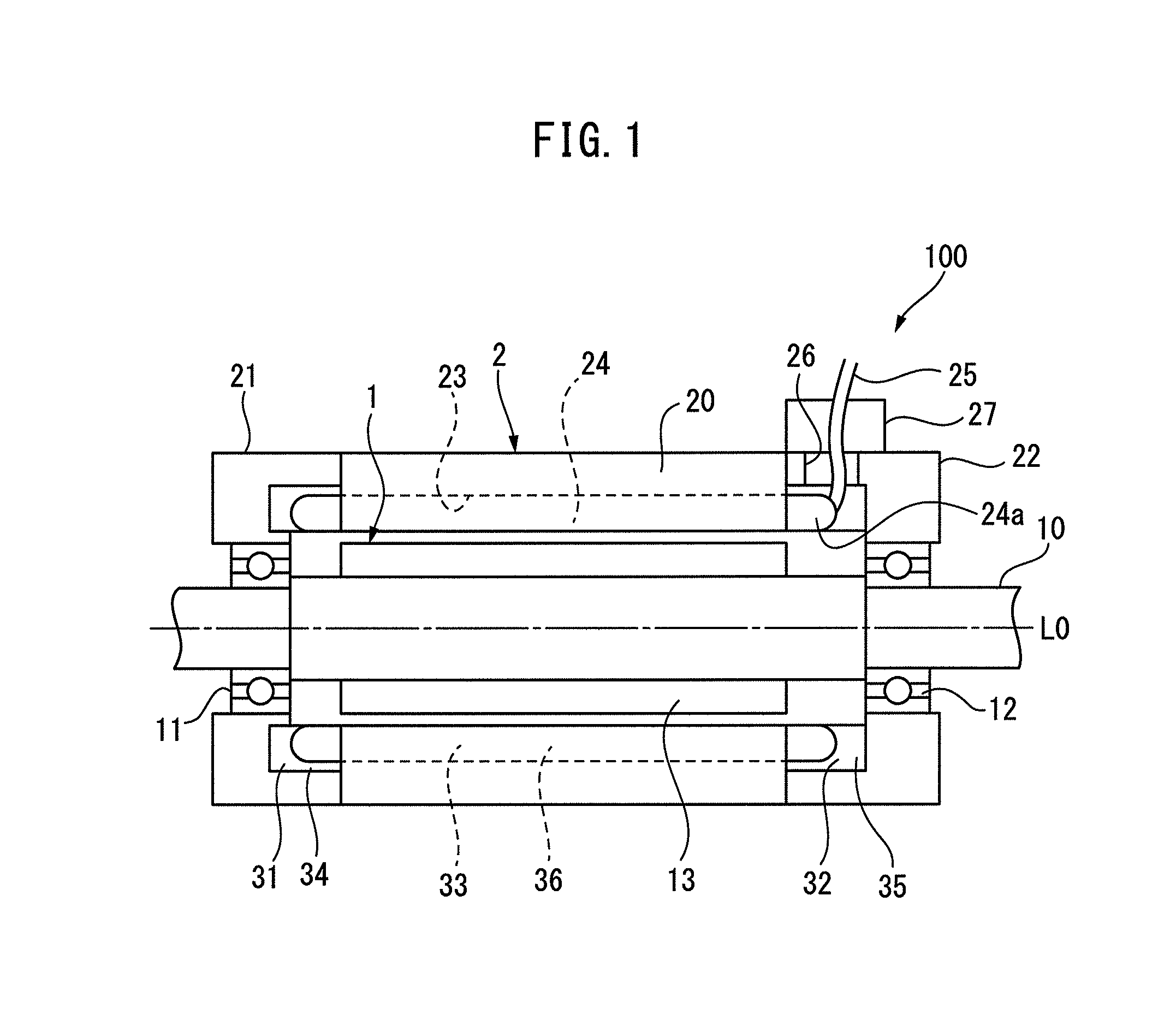
[0020]Embodiments of the present invention will be described below with reference to FIG. 1 to FIG. 8. FIG. 1 is a cross-sectional view that schematically illustrates the internal structure of an electric motor 100 according to an embodiment of the present invention. The electric motor 100 is a three-phase induction motor including a rotor 1 and a stator 2, and is used, for example, for driving a spindle of a working machine.

[0021]As illustrated in FIG. 1, the rotor 1 includes a rotating shaft 10 which extends along a central axis L0, and both ends of the rotating shaft 10 are rotatably supported by bearings 11 and 12, respectively. A rotor core 13 formed by layering plural electromagnetic steel sheets is integrally attached to the rotating shaft 10. Plural slot holes parallel to the axis L0 are formed in the rotor core 13. A metal rod or a metal is filled in each slot hole. These metal rods or metals are short-circuited by a short-circuit ring on both ends thereof. Hereinafter, the...


PUM

PropertyMeasurementUnit
Areaaaaaaaaaaa
Expansion enthalpyaaaaaaaaaa

Abstract

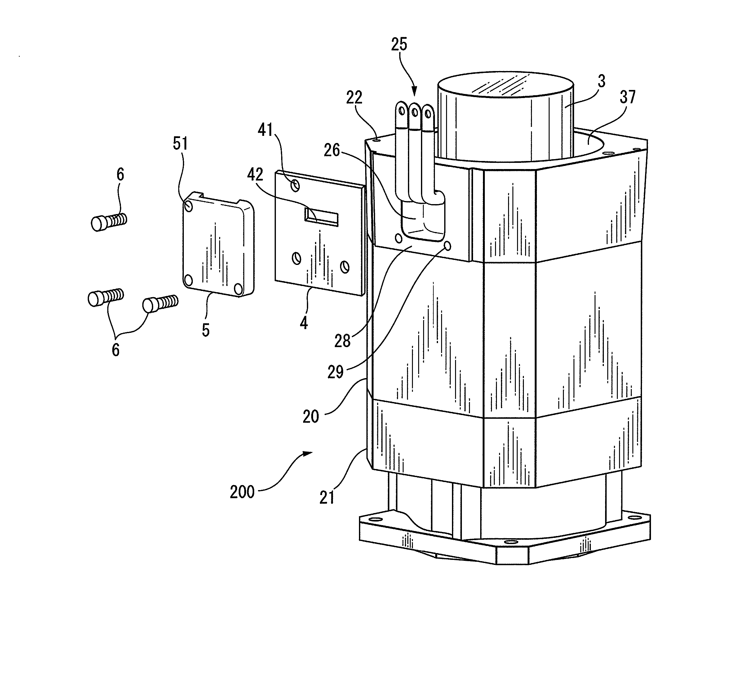
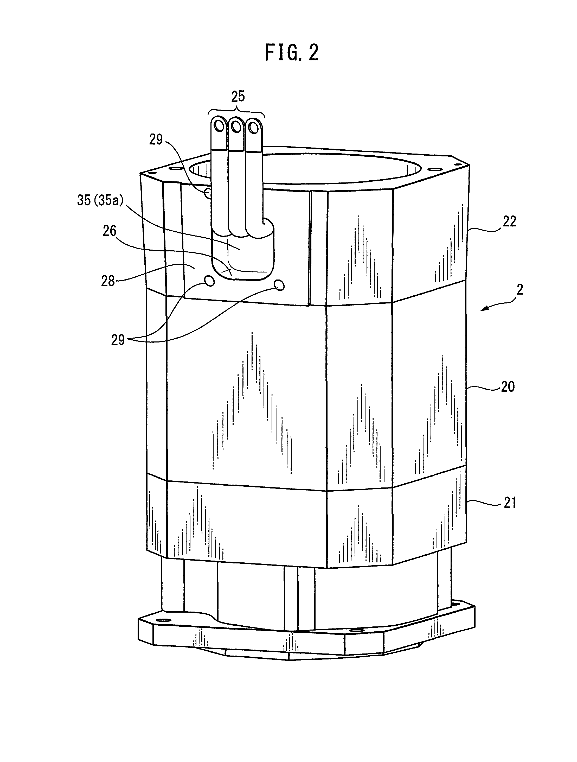
A method for manufacturing an electric motor stator, including: attaching a hollow bracket to an end of a hollow stator core and allowing a lead connected to the winding to pass through an opening formed in a peripheral surface of the bracket to take out the lead to an outside of the bracket; placing a core material inside the stator core and the bracket; attaching a sealing member to an outer peripheral surface of the bracket so as to block the opening while allowing the lead to pass through the through-hole; and filling a molten resin into an annular space between the stator core and the core material and between the bracket and the core material, to form a resin unit.

Description

BACKGROUND OF THE INVENTION[0001]1. Field of the Invention[0002]The present invention relates to a method for manufacturing an electric motor stator including a resin-molded unit, to an electric motor stator, and to an electric motor.[0003]2. Description of the Related Art[0004]As a method for manufacturing such an electric motor stator, for example, a method described in Japanese Laid-open Patent Publication No. 5-56611 (JP 5-056611 A) has been known. In the method described in JP 5-056611 A, brackets are attached to both ends of a hollow stator core to form a stator, and the stator is installed upright between upper and lower dies. A core material is installed upright from the lower die and is inserted into the insides of the stator core and the brackets. In this state, a resin is injected by pressurization through a resin inlet formed in the lower bracket, and the resin is filled between the stator core and the core material and between the brackets and the core material, to form...

Claims


Application Information

Patent Timeline
IPC IPC(8): H02K3/38H02K15/00
CPCH02K3/38H02K15/0043H02K5/08H02K5/10H02K5/225H02K15/02H02K15/12H02K15/14Y10T29/49009
Inventor KAMIYA, YOUHEI
Owner FANUC LTD
Learn More