Driving member, linear driving device, camera, device and electronic device

a technology of driving shaft and driving member, which is applied in the direction of mountings, instruments, television systems, etc., can solve the problems of the lens support moving, and achieve the effect of improving the driving capability of the driving shaft, increasing the driving capability, and increasing the driving force and driving amount that can be obtained by vibrating the driving sha

Active Publication Date: 2014-12-11
NEW SHICOH MOTOR CO LTD
View PDF13 Cites 9 Cited by
  • Summary
  • Abstract
  • Description
  • Claims
  • Application Information

AI Technical Summary

Benefits of technology

[0019]One of the advantages of the present invention is to provide the driving member that permits the driving shaft to provide the increased driving capability, or more specifically, that allows the driving force and driving amount that can be obtained by vibrating the driving s

Problems solved by technology

Then, this will cause t

Method used


Image

  • Driving member, linear driving device, camera, device and electronic device
  • Driving member, linear driving device, camera, device and electronic device
  • Driving member, linear driving device, camera, device and electronic device

Examples


embodiment 1

[0028]The embodiment 1 of the present invention will be described by referring to the appropriate figures in the accompanying drawings.

[0029]A driving member 10 according to the embodiment 1 can be used with a linear driving device that may be incorporated in a camera or digital camera mounted on an electronic device such as the mobile phone and the like.

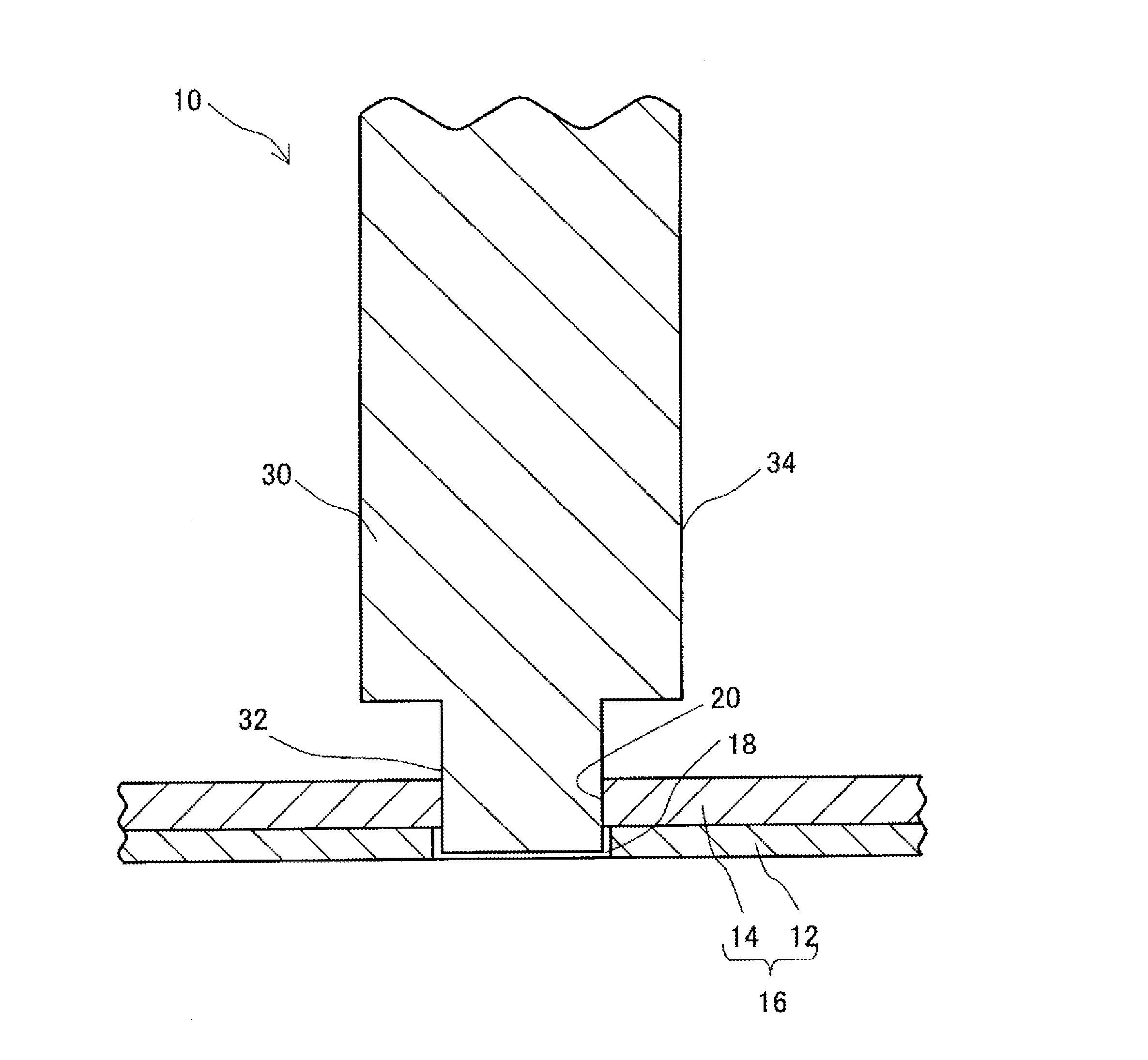
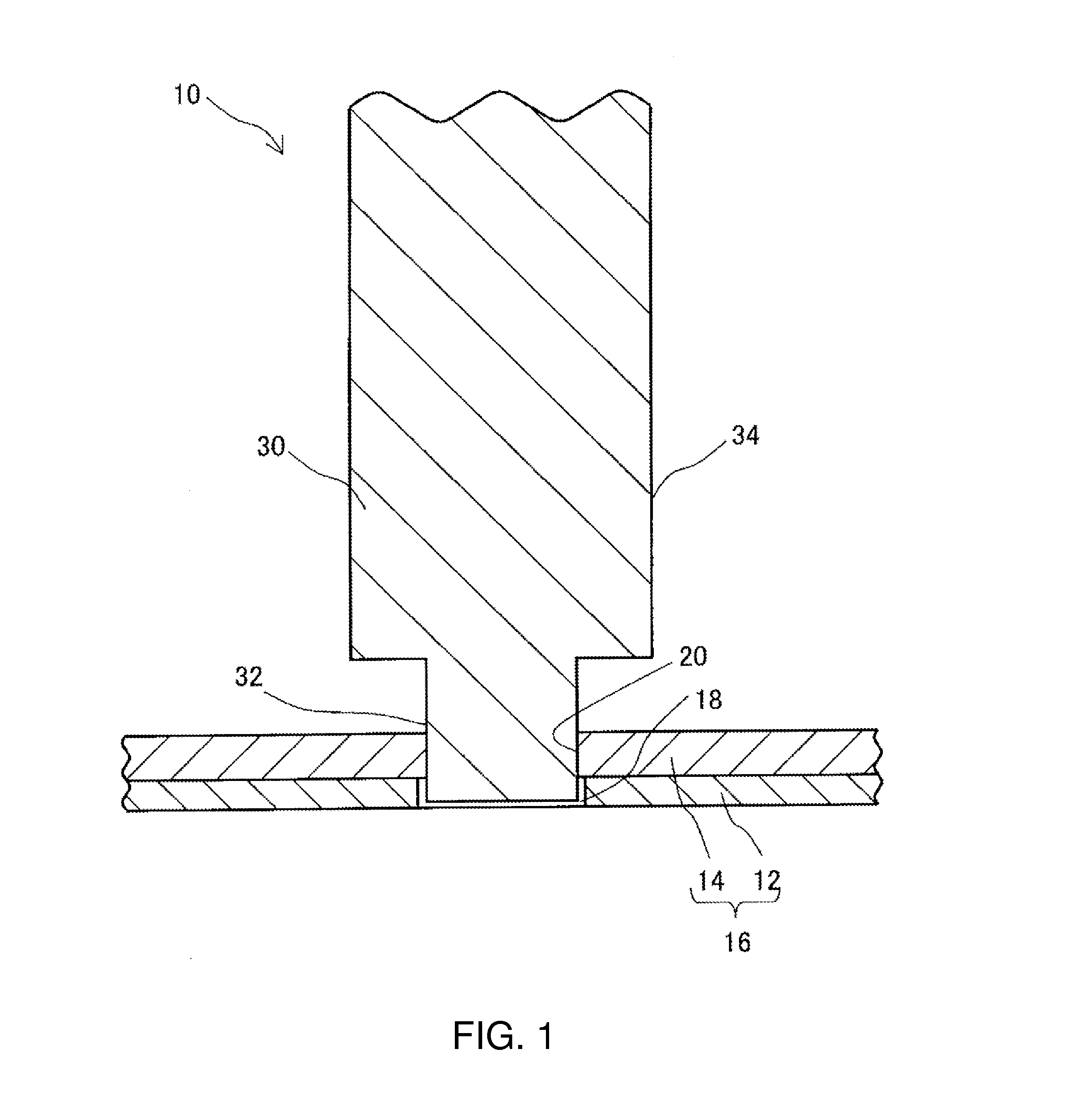
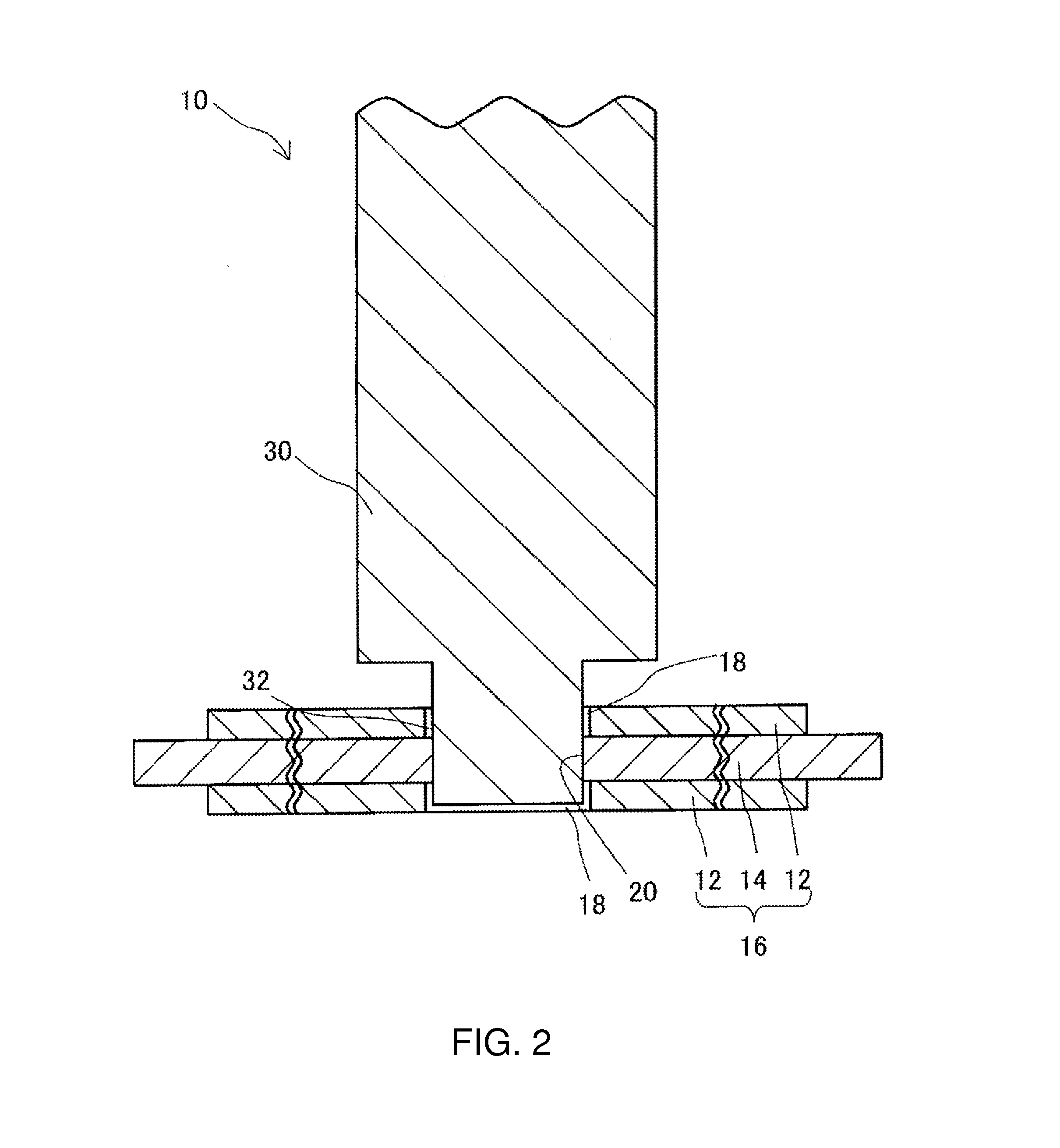
[0030]Firstly, the general description of the driving member 10 according to the embodiment 1 of the present invention is presented. The driving member 10 includes a deformable thin plate 16 and a driving shaft 30. The deformable thin plate 16 includes a flexible thin plate 12 that may expand and contract itself under the applied voltage and an elastic thin plate 14 having at least one side thereof rigidly fixed to the flexible thin plate 12. In the form of the driving member 10 shown, the elastic thin plate 14 has its bottom side rigidly fixed to the flexible thin plate 12.

[0031]The driving shaft 30 has its one axial end thereof ri...

embodiment 2

[0096]The embodiment 2 of the present invention will be described below by referring to the appropriate figures in the accompanying drawings. It should be noted that those component parts or elements which are similar to those in the embodiment 1 are given like reference numerals. To avoid the duplicate description, the description of those parts or elements is omitted.

[0097]The driving member 10 in the embodiment 2 further includes an intervening thin plate 40 that is interposed between the inner side portion of the through hole on the deformable thin plate 16 and the corresponding lateral side portion 32 of the end of the driving shaft 30.

[0098]In the structure according to the embodiment shown and described in FIG. 4, an intervening thin plate 40 is added to the structure shown in FIG. 1.

[0099]The intervening thin plate 40 may be made of any of the metallic material, the synthetic resin material, the ceramics material and the like.

[0100]The intervening thin plate 40 is provided s...

embodiment 3

[0116]The embodiment 3 of the present invention will be described below by referring to the appropriate figures in the accompanying drawings. It should be noted that those component parts or elements which are similar to those in the embodiment 1 are given like reference numerals. To avoid the duplicate description, the description of those parts or elements is omitted.

[0117]As shown in FIG. 5, the embodiment 3 is provided for explaining a linear driving device 50 using the driving member 10 in the embodiments 1 and 2, a camera device 90 using the driving member 10 and an electronic device 95.

[0118]The lens driving device that includes the linear driving device 50 using the driving member 10 is used to drive the zooming lens and focusing lens in the camera device 90.

[0119]The camera device 90 may be incorporated in any one of the various types of the electronic device 95. As typical examples, the electronic device 95 includes the mobile terminal that is represented by the cellular o...


PUM


Abstract

A driving member, a linear driving device using the driving member, a camera device and an electronic device are provided. The driving member (10) includes a deformable thin plate (16) having a flexible thin plate (12) capable of expanding and contracting itself under the applied voltage and an elastic thin plate (14) having at least one side thereof rigidly fixed to the flexible thin plate (12) and a driving shaft (30) having its one axial end rigidly fixed to the deformable thin plate (16) and being capable of undergoing displacements that are operatively associated with the deformation of the deformable thin plate (16), wherein the driving shaft (30) has the lateral side portion (32) of the one axial end thereof rigidly fixed to the corresponding inner side portion of a through hole formed on the deformable thin plate (16).

Description

BACKGROUND OF THE INVENTION[0001]1. Field of the Invention[0002]The present invention relates to a driving member for use with a linear driving device that is employed in the camera or digital camera usually mounted on an electronic device such as the mobile phone and the like. The present invention also relates to a linear driving device, a camera device and an electronic device, each of which uses the driving member of the present invention.[0003]2. Description of Relevant Art[0004]In the conventional relevant art, the small-size camera device or the like employs the linear driving device (the lens driving device) that is designed for use in driving the lens mounted on the camera device. There are various types of the driving member that have been used with the linear driving device (the lens driving device).[0005]As one example of the driving member, there has been a zooming or focusing type of the driving member that drives the lens support having the lens mounted thereon to be ...

Claims


Application Information

Patent Timeline
IPC IPC(8): G02B7/04H04N5/225
CPCH04N5/2254G02B7/04G02B7/10H04N23/57H04N23/55
Inventor TADA, JUNICHISHIRAKI, MANABU
Owner NEW SHICOH MOTOR CO LTD
Why Eureka
Try Eureka