Glass wiper

a wiper and glass technology, applied in the field of cleaning apparatus, can solve the problems of inconvenient and unreasonable connection of external water pipes and taps for water spraying, low work efficiency, and hand discomfort, and achieve the effects of convenient operation, simple and reasonable structure, and avoiding wrist fatigu

Active Publication Date: 2014-12-18
NINGBO BEARI PLASTIC PROD & ELECTRIC APPLIANCE CO LTD
View PDF6 Cites 4 Cited by
  • Summary
  • Abstract
  • Description
  • Claims
  • Application Information

AI Technical Summary

Benefits of technology

[0019]Compared with the prior art, in the present invention, the windows wiper is provided with the scraping bar and the wiping board with the fixed wiping towel, which may perform the functions of both scraping and wiping at the same time; in addition, the windows wiper has few portions, thereby resulting in a simple and reasonable structure; when the wiping board is rotated backward to the horizontal state, the wiping board can not be continuously rotated backward after the bottom surface of the wiping board contacts with the upper surface of the transverse portion. When the wiping board is rotated forward to the vertical state, the wiping towel in the wiping board can be used for wiping the wiped glass surface. The vertical portion of the base body can be griped by the operator so that the action direction can be basically parallel with the vertical portion of the base body when using the scraping bar to scrap the glass or using the wiping towel in the wiping board to wipe, thereby resulting in a convenient operation; besides, the wiping board can be rotated against the base body. As the angle between the glass and arms will keep changing during wiping the glass with the wiping towel, the shaft can ensure that the wiping board will keep stuck with the glass, regardless of the angle change of the arms, avoiding tiredness on wrists. If the windows wiper is with the shaft, the wrists should be rotated to keep the wiping board stuck to the glass which will cause tiredness on wrists.

Problems solved by technology

It is not only inconvenient but also probable for the operator to forget carrying one of the tools, resulting in low work efficiency.
As the wiping angle between the brush holder and the glass and that between the supporting shaft and the glass are not parallel, the hands will feel uncomfortable.
In addition, it is inconvenient and unreasonable to connect any external water pipe and tap for water spraying.

Method used


Image

  • Glass wiper
  • Glass wiper
  • Glass wiper

Examples


Embodiment Construction

[0031]To enable a further understanding of the innovative and technological content of the invention herein refer to the detailed description of the invention and the accompanying drawings below:

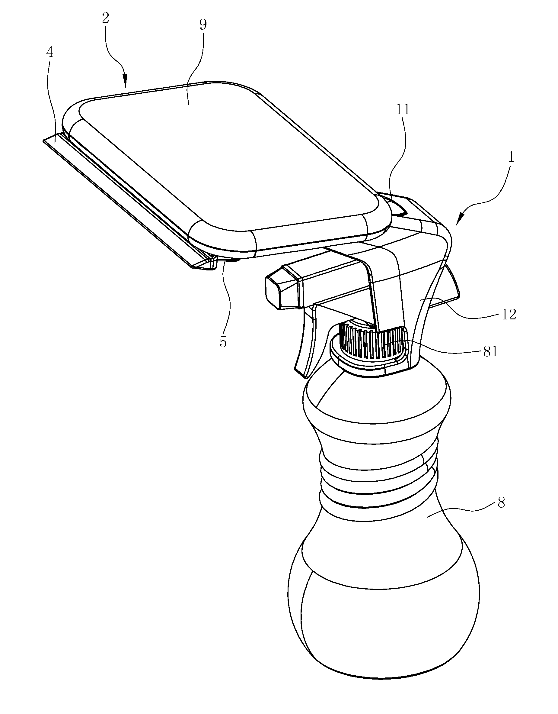
[0032]FIG. 1 and FIG. 10 show a preferred embodiment of the present invention.

[0033]The windows wiper comprises:

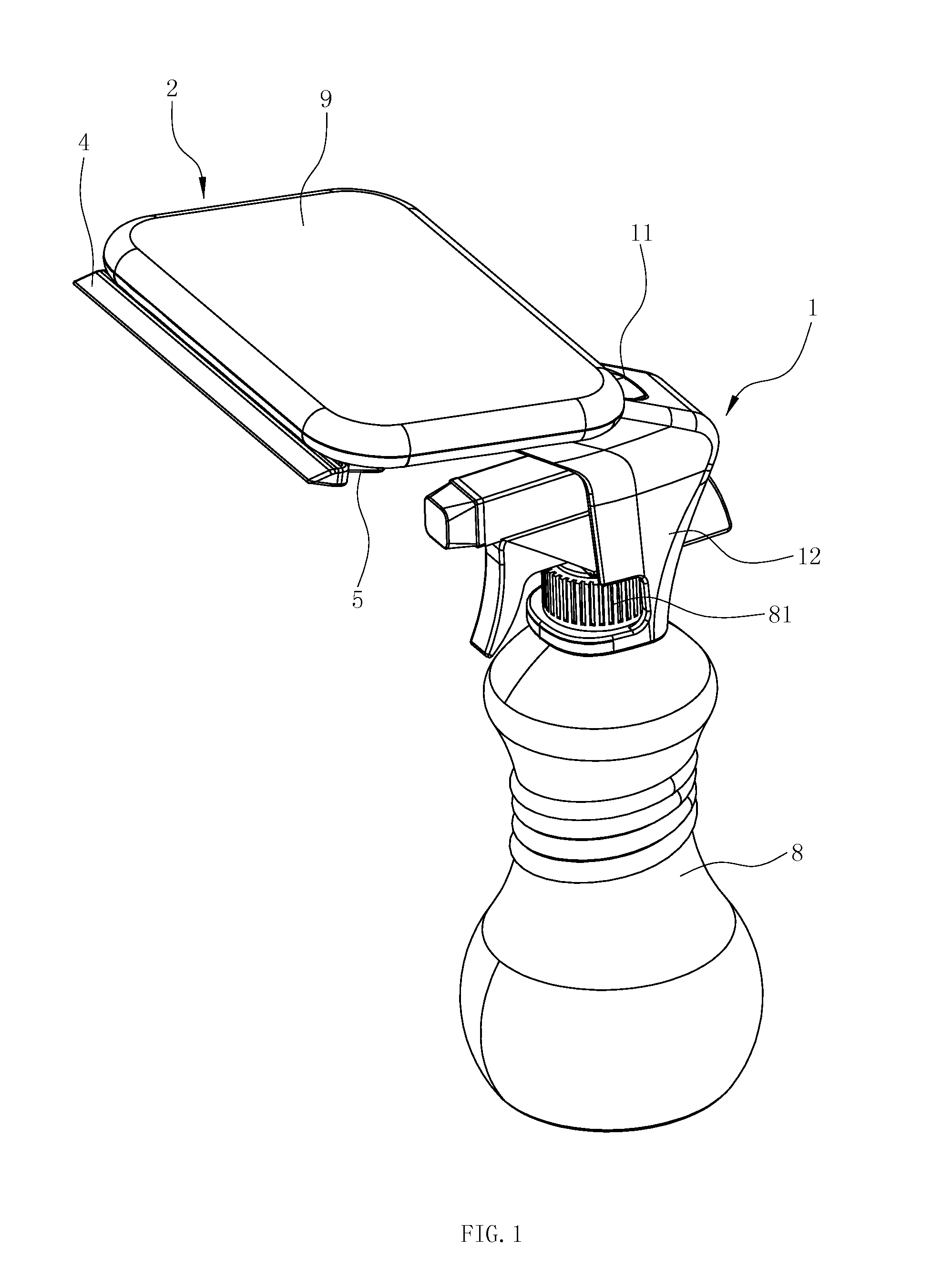
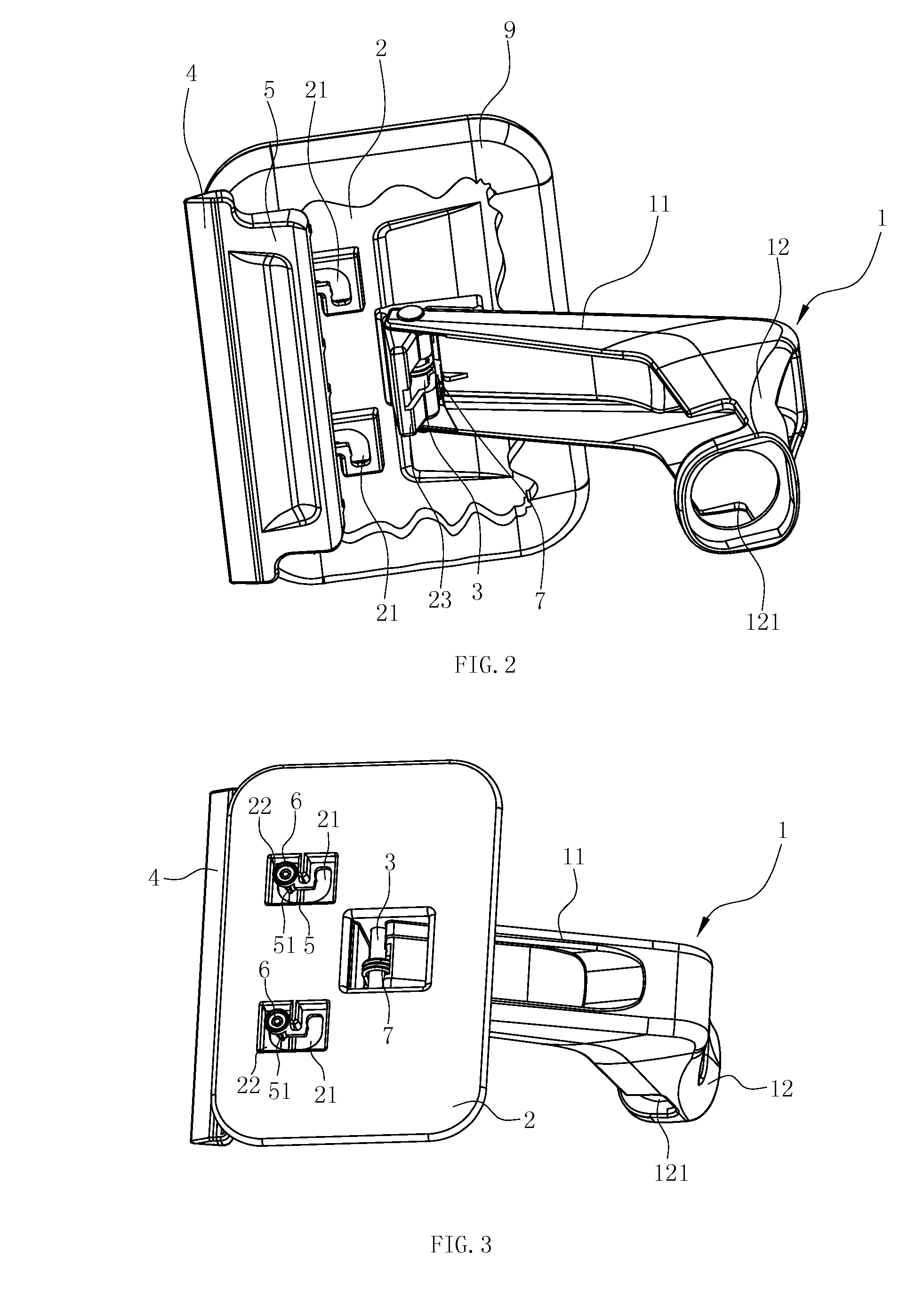
[0034]A base body 1 convenient to hold with hands is provided, as shown in FIG. 10, consisting of a transverse portion 11 and a vertical portion 12;

[0035]A wiping board 2 used for fixing a wiping towel 9 is rectangle in shape. The wiping towel 9 is installed on the wiping board 2, the middle portion of which is connected to the front end of the transverse portion 11 through the rotation of the shaft 3. The middle portion of the lower end surface on the wiping board 2 is provided with the inserting portion 23 extended downward, and the transverse portion 11 of the base body is provided with a gap 13. The inserting portion 23 is inserted downward into the gap 13 and connected into th...


PUM


Abstract

The present invention provides a windows wiper, which comprises a base body with a transverse portion and a vertical portion, a wiping board, a bottom board fixed with a scraping bar; the middle portion of the wiping board is rotatably connected with a front end of the transverse portion through a shaft; the bottom board is disposed under the wiping board. The windows wiper of the present invention has the two functions of scraping and wiping. The number of components of the windows wiper is small, and the structure is simple too. Furthermore, when the scraping bar is used to scrape the glass or the wiping towel on the wiping board is used to wipe the glass, the direction of operation is parallel to the vertical portion of the base body, which makes the operation convenient.

Description

RELATE APPLICATION [0001]This application is a national phase entrance of and claims benefit to PCT Application for a windows wiper, PCT / CN2012 / 000149, filed on Feb. 7, 2012, which claims benefit to Chinese Patent Application 201210016736.9, filed on Jan. 19, 2012. The specifications of both applications are incorporated here by this reference.FIELD OF THE INVENTION[0002]The present invention relates to a kind of cleaning apparatus for daily use, in particular, to a kind of windows wiper which is used for windows cleaning.DESCRIPTION OF THE PRIOR ART [0003]There are mainly two kinds of traditional windows wipers: One is the window brush which consists of a brush holder and a wiping towel fixed on the brush holder; and the other is a scraping tool with a flexible adhesive tape mainly used for scraping and cleaning the glass, e.g. a Chinese patent CN200998226Y with the title “A Windows wiper” whose patent No. is ZL200720004365.7, and another Chinese patent CN200960089Y with the title ...

Claims


Application Information

Patent Timeline
Patent Type & Authority Applications(United States)
IPC IPC(8): A47L1/08
CPCA47L1/08A47L1/06A47L13/08
Inventor LIU, WENGAO
Owner NINGBO BEARI PLASTIC PROD & ELECTRIC APPLIANCE CO LTD
Why Eureka
Try Eureka