Sensor fusion for depth estimation

Active Publication Date: 2014-12-18
DISNEY ENTERPRISES INC
View PDF3 Cites 38 Cited by
  • Summary
  • Abstract
  • Description
  • Claims
  • Application Information

AI Technical Summary

Problems solved by technology

However, ToF sensors, especially inexpensive ones, may not provide a depth measurements at a resolution level sufficient to support the depth map computation of

Method used


Image

  • Sensor fusion for depth estimation
  • Sensor fusion for depth estimation
  • Sensor fusion for depth estimation

Examples


Embodiment Construction

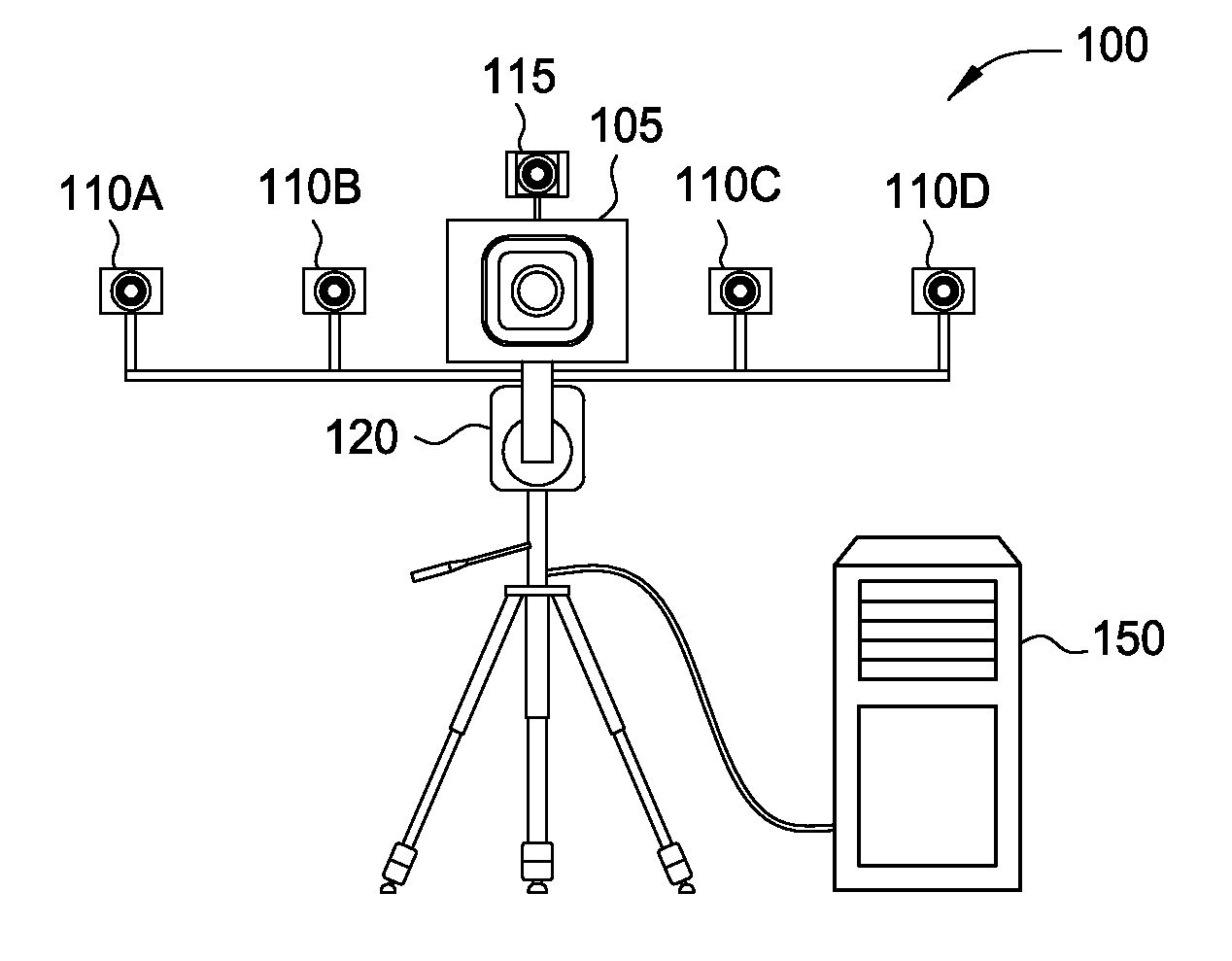
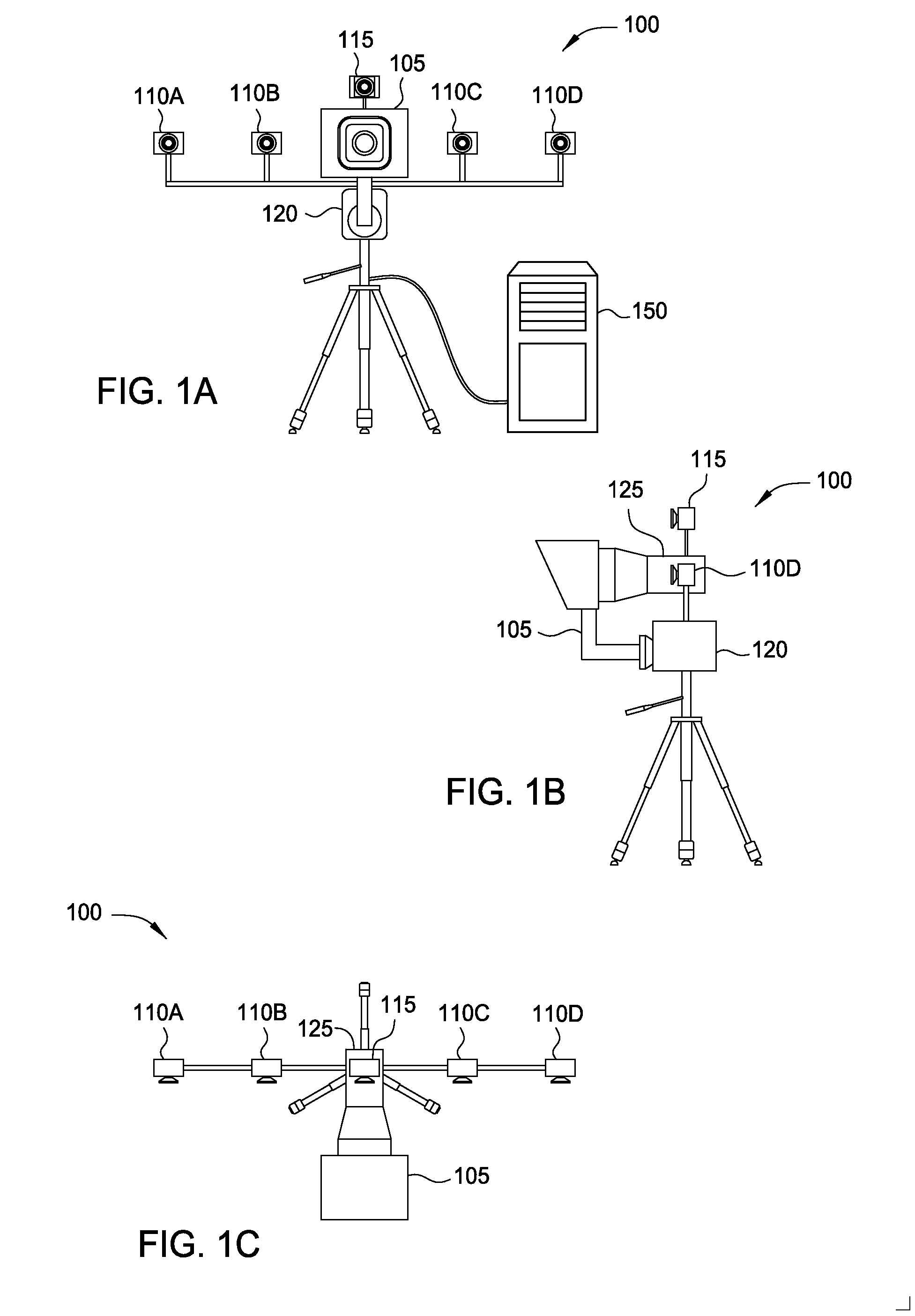
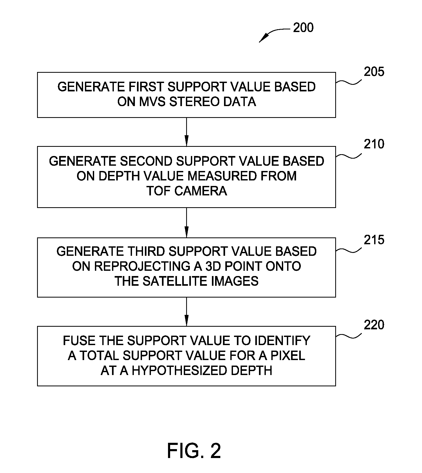
[0018]To generate a pixel-accurate depth map, in one embodiment, ToF data from a range-estimation sensor (e.g., a ToF sensor) is combined with data from multiple cameras to produce a high-quality depth measurement for pixels in an image. To do so, a depth measurement system may use a plurality of cameras mounted on a support structure to perform a depth hypothesis technique (e.g., plane sweeping) to generate a first depth-support value. Furthermore, the apparatus may include a mounted ToF sensor which generates a second depth-support value based on depth estimates provided in the ToF data. In addition, the depth measurement system may project a 3D point (i.e., a pixel at a particular depth) from a reference image captured by a reference camera onto an auxiliary image captured by one or more auxiliary cameras. By comparing the color of the corresponding pixels in the auxiliary image with the color of the 3D point in the reference image, the system generates a third depth-support valu...


PUM


Abstract

To generate a pixel-accurate depth map, data from a range-estimation sensor (e.g., a time-of flight sensor) is combined with data from multiple cameras to produce a high-quality depth measurement for pixels in an image. To do so, a depth measurement system may use a plurality of cameras mounted on a support structure to perform a depth hypothesis technique to generate a first depth-support value. Furthermore, the apparatus may include a range-estimation sensor which generates a second depth-support value. In addition, the system may project a 3D point onto the auxiliary cameras and compare the color of the associated pixel in the auxiliary camera with the color of the pixel in reference camera to generate a third depth-support value. The system may combine these support values for each pixel in an image to determine respective depth values. Using these values, the system may generate a depth map for the image.

Description

BACKGROUND[0001]1. Field of the Invention[0002]Embodiments presented in this disclosure generally relate to generating depth maps, and more specifically, to generating depth maps by fusing data received from sensors of different modalities.[0003]2. Description of the Related Art[0004]A computing device may be coupled to a camera or a combination of sensors to assist in producing higher quality images or in reconstructing a scene. One way of accomplishing this is by performing depth sensing where the distance between a point in a scene and a camera (usually a reference camera) is determined. By measuring the depth for a plurality of pixels in a reference image, a depth map for the reference image may be acquired.[0005]To measure depth, some systems use a time of flight (ToF) sensor. ToF sensors send out light and measure the time it takes for the light to travel from the sensor to an object, and then back to the sensor. By measuring this round-trip travel time, the distance from a pl...

Claims


Application Information

Patent Timeline
IPC IPC(8): G06T7/00H04N13/00G01S17/86G01S17/894
CPCH04N13/0022G06T7/0075G06T2200/04G06T2207/10012G06T2207/10028G06T2207/20221G06T7/593G01S17/86G01S17/894G06T15/10
Inventor VAN BAAR, JEROENBEARDSLEY, PAUL A.POLLEFEYS, MARCGROSS, MARKUS
Owner DISNEY ENTERPRISES INC
Why Eureka
Try Eureka