Remote charging system

a charging system and remote charging technology, applied in the direction of charging devices, exchanging data, transportation and packaging, etc., can solve the problems of implanted devices such as heart pacemakers, battery replacement may be life-threatening, and even greater inconvenien

Active Publication Date: 2014-12-25
HUMAVOX
View PDF3 Cites 282 Cited by
  • Summary
  • Abstract
  • Description
  • Claims
  • Application Information

AI Technical Summary

Problems solved by technology

When it comes to medical device the nuisance is even greater and in some cases replacement of a battery may be a life threatening procedure.
Replacing the batteries in the implanted device, such as heart pace maker, requires surgery associated with risk, discomfort and cost.
In addition, since the energy in the implanted device is so expensive, physicians compromise on their requirements, and important features like collecting data from the implanted device are done in long time intervals in order to save the energy.
Thus, it becomes a nuisance to the user.

Method used


Image

  • Remote charging system
  • Remote charging system
  • Remote charging system

Examples


Embodiment Construction

[0039]Although various features of the disclosure may be described in the context of a single embodiment, the features may also be provided separately or in any suitable combination. Conversely, although the disclosure may be described herein in the context of separate embodiments for clarity, the disclosure may also be implemented in a single embodiment. Furthermore, it should be understood that the disclosure can be carried out or practiced in various ways, and that the disclosure can be implemented in embodiments other than the exemplary ones described herein below. The descriptions, examples and materials presented in the description, as well as in the claims, should not be construed as limiting, but rather as illustrative.

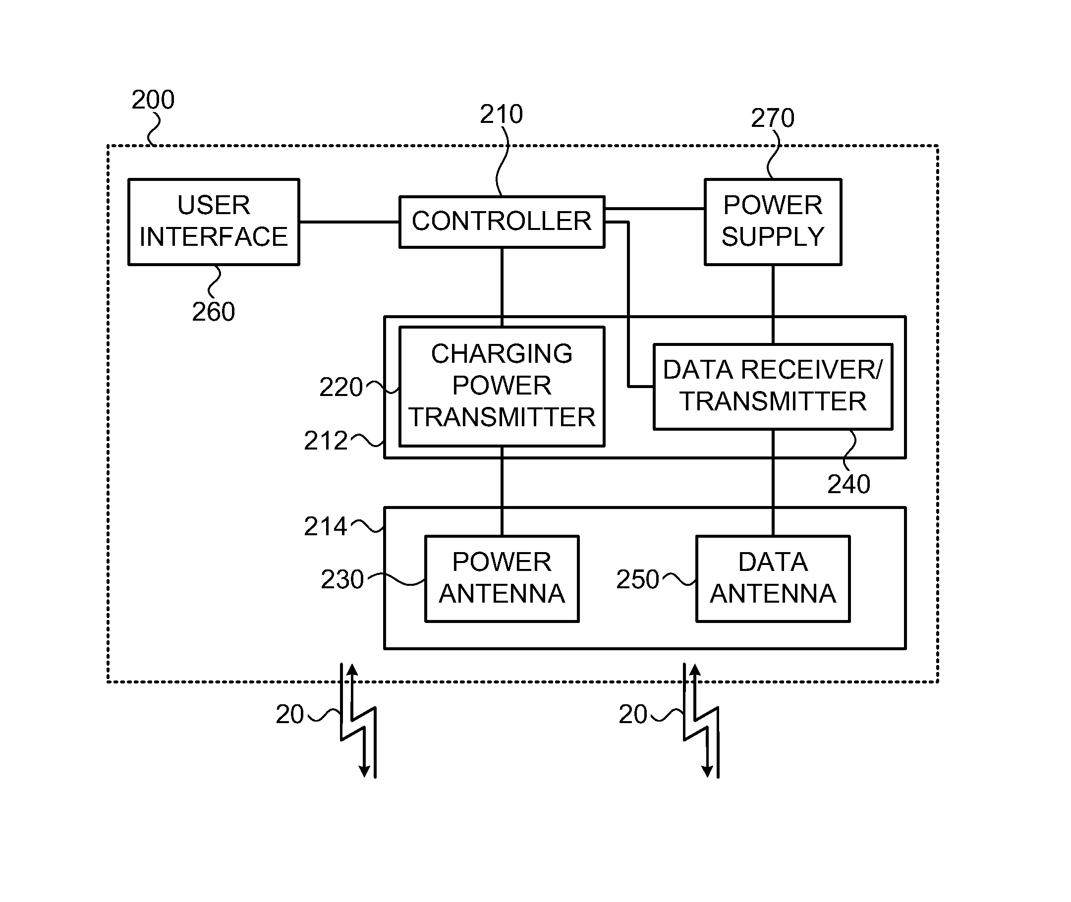
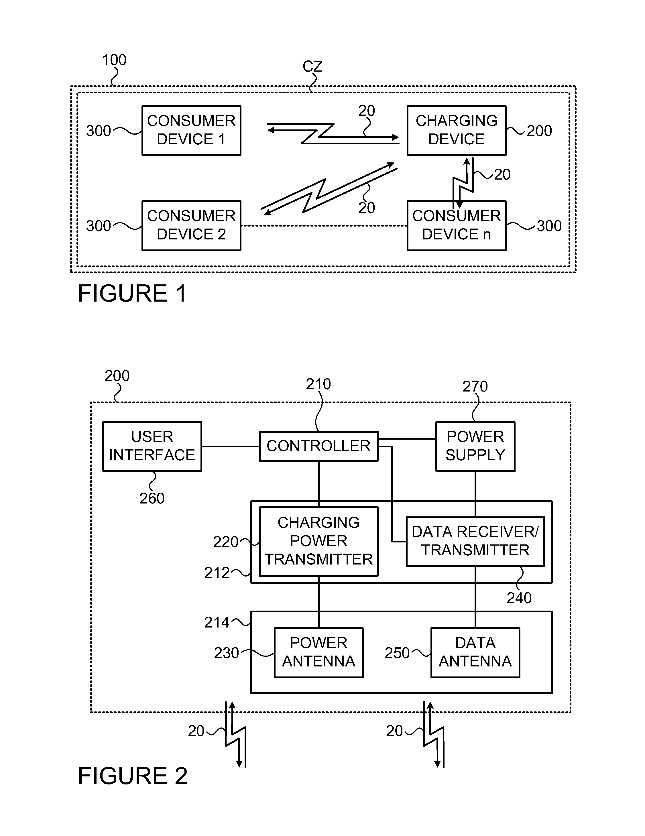
[0040]Reference is made to FIG. 1 which is a schematic illustration of a charging system 100 for remote charging of multiple consumers 300 according to the consumers demand. The system 100 includes one or more charging devices each defining its charging zone, ...


PUM


Abstract

A charging device (200) is provided for communicating with one or more consumer devices (300) for remotely charging at least one of them upon demand of the consumer. The charging device (200) comprises a transmitter unit associated with an antenna unit comprising a power antenna configured to define at least one charging zone for transmitting charging power to the at least one charging zone; a receiver for receiving signals from consumers (300) located within the charging zone; and a controller unit. The controller is configured and operable to be responsive to a request signal from a consumer (300) indicative of demand for charging, to initiate a charging process of the consumer by radiation from the power antenna toward said consumer (300) to supply power required for operating a functional unit of said consumer (300). The power antenna may comprise an array of directional antenna elements, each defining the charging zone within a different angular segment of entire charging space defined by a radiation pattern of the antenna array.

Description

TECHNOLOGICAL FIELD AND BACKGROUND[0001]The present invention relates to a remote charging system and method for charging one or more electronic devices in at least one consumer's side.[0002]There are many devices that use electricity as their energy source, but due to their mobility needs they use batteries as their energy supplier. Such energy consumers may include computer mouse, television remote control, DVD remote control, air condition remote control, shaver, electrical tooth brash, wireless line phone extension, camera, etc. Each such consumer needs a periodical replacement of its battery. Since batteries are pollution sources, and since their replacement is tiresome (you need to keep stock; you need to replace; you need to throw them to a specific garbage container) there is a need for a system that will charge the consumers without the need of the user to do anything.[0003]When it comes to medical device the nuisance is even greater and in some cases replacement of a batte...

Claims


Application Information

Patent Timeline
Patent Type & Authority Applications(United States)
IPC IPC(8): H02J7/00H02J7/02
CPCH02J7/0021H02J7/0052H02J7/0042H02J7/025H02J7/007H02J50/23H02J50/27H02J50/80H02J50/90H02J7/00034H02J50/402H02J50/001H02J7/00
Inventor MANOVA-ELSSIBONY, ASAFGALAN, ODED
Owner HUMAVOX
Why Eureka
Try Eureka