
Variable brake light control system using user terminal, and method for controlling the same

Inactive Publication Date: 2014-12-25
LEE IN OK
View PDF5 Cites 18 Cited by
  • Summary
  • Abstract
  • Description
  • Claims
  • Application Information

AI Technical Summary

Benefits of technology

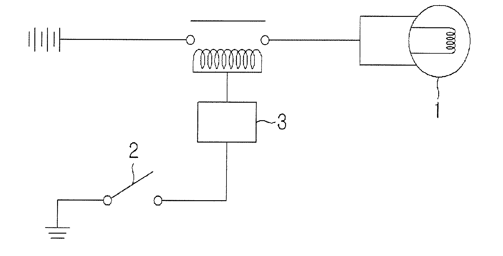
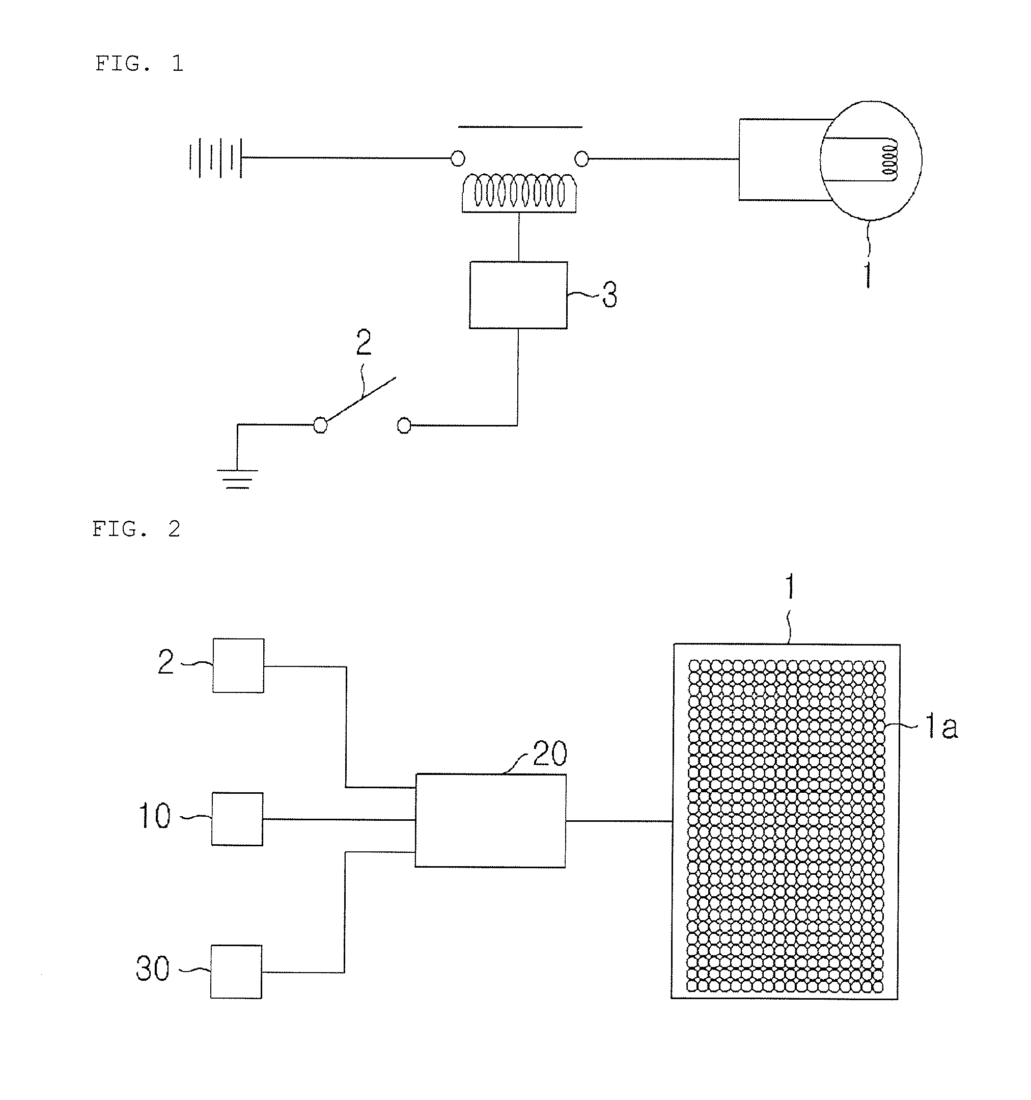
The present invention is a brake light system that can be controlled by the driver through a selecting means. Once the driver selects a signal, the control unit outputs the designs or color of the shape or patterns that the driver selects to the lighting unit to light it up. This helps the driver recognize that the brakes are lit up and also provides a new feeling. Additionally, the invention allows the driver to input various types of information and display them in real-time on the brake light of their vehicle. This can include advertisements or images that the driver wishes to show. Furthermore, the invention can easily notice dangerous situations or information that the driver wishes to inform to the following driver by reflecting the patterns of the brake light that the driver wishes in real-time.

Problems solved by technology

Furthermore, there is problem that, when an emergency occurs substantially, it is difficult for the driver of the follow-up vehicle to recognize the situation accurately.
Therefore, it may be occurred problem that it is difficult to distinguish exactly the state in case of that the brake lights are lit by stepping the brake pedal and the state in case of that the rear light is lit.

Method used


Image

  • Variable brake light control system using user terminal, and method for controlling the same
  • Variable brake light control system using user terminal, and method for controlling the same
  • Variable brake light control system using user terminal, and method for controlling the same

Examples


first embodiment

[0057]Since such variable brake light make it possible for the driver to input the selection signal unlike the first embodiment which the driver input the selection signal by operating the selection switch, it offer a comfortable advantages at easy-to-use. In particular, the selection signal can be simply inputted during driving so that it can be more convenient to use, and there is advantageous that it can prevent from being disturbed the security driving since it is not necessary to view the selection switch for operating it during the driving.

third embodiment

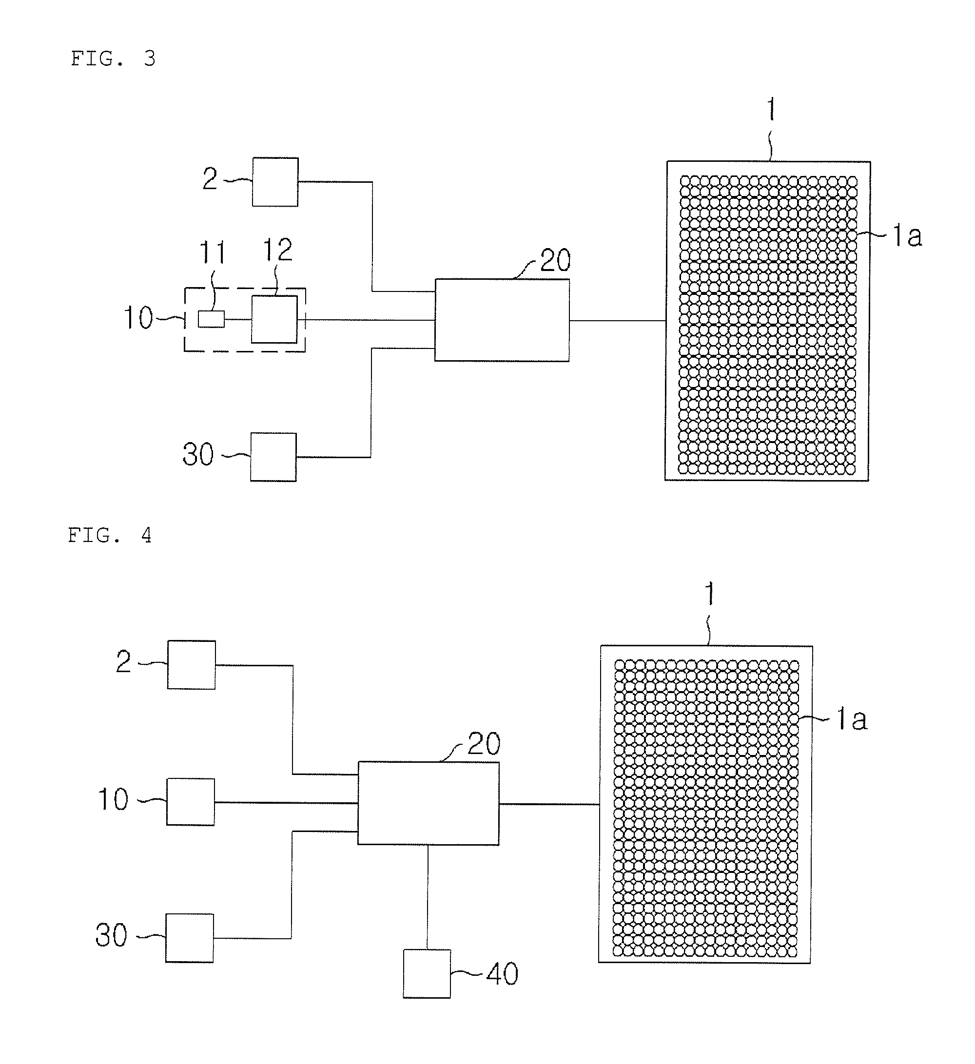
[0058]FIG. 4 illustrates the third embodiment according to the invention, wherein it further comprises a GPS (40) which is connected to the said control unit (20) and outputs information such as position and velocity or acceleration of the vehicle.

[0059]Then, it is configured such that the said control unit (20) receives the data for velocity and acceleration being outputted from the said GPS (40), and then outputs the data of specific designs or colors to the lighting unit (1) in case that the vehicle is suddenly stopped or traveled at the road of steep slope or sharp curves. At this time, the said data of specific designs or colors being outputted from the control unit (20) may be any one that is selected by the driver or that is preset depending on the situation. In other words, when you stop at emergency, flickering mark such as emergency lamp can be outputted, and when driving at a sharp curves or steep slope, a preset deceleration-induced light can be outputted.

[0060]In this c...


PUM


Abstract

The present invention relates to a variable brake light in which a lighting unit can be illuminated in a variety of shapes according to a vehicle operating state or the selection of a driver. The variable brake light comprises: a lighting unit consisting of LED lamps in which a plurality of LEDs are arranged in a brake light according to a specific pattern so as to display designs having various shapes or patterns; a user terminal in which an application program is installed, comprising pattern input means for inputting a brake light pattern using the installed application program, and which transmits the input pattern information to the brake light through wireless communication means; and a brake light control device for receiving the pattern information from the user terminal through the wireless communication means, generating a control signal for controlling flashing of each LED lamp of the lighting unit according to the received pattern information, and transmitting the control signal to the lighting unit.

Description

BACKGROUND OF THE INVENTION[0001]1. Field of the Invention[0002]The present invention relates to a brake light control system and method for controlling the same, and more particularly to a variable brake light control system using user terminal in which the lighting unit of brake light of the corresponding vehicle can be illuminated in a variety of shapes according to an input of lighting pattern of a brake light via user terminal and method for controlling the variable brake light control system.[0003]2. Description of the Prior Art[0004]In general, the brake light of vehicle has function that informs the driver of the following up vehicle that a brake pedal is pressed by lighting on of the brake light when the operator operate brake.[0005]For this purpose, the brake light control apparatus is composed of a lighting unit which is installed in the rear of the vehicle, and a detection switch which is connected to the brake pedal of vehicle and operated with on when the driver pressi...

Claims


Application Information

Patent Timeline
IPC IPC(8): B60Q1/44
CPCB60Q1/441B60Q1/444H04M1/72415B60Q2900/50B60Q11/00B60Q1/44
Inventor LEE, JUN SEOK
Owner LEE IN OK
Learn More