
Remote Control Attachment For Image Capturing Equipment

a technology of remote control and image capturing equipment, which is applied in the direction of color television details, television systems, instruments, etc., can solve the problems of expensive equipment, poor image quality, and inability to effectively capture one's own imag

Inactive Publication Date: 2014-12-25
MARSHALL PAUL STEPHEN
View PDF3 Cites 0 Cited by
  • Summary
  • Abstract
  • Description
  • Claims
  • Application Information

AI Technical Summary

Benefits of technology

The invention is a device that can be attached to image capturing equipment to remotely control the shutter release and capture images. It solves problems with manually operated equipment, such as shaking, and is also effective at a distance from the operator. The device uses a force to activate the shutter release, and can be attached to a wide range of equipment without needing to modify it. It can be used with both compact digital cameras and mobile phones. The device is controlled by a key fob remote controller and an attachment part that can be fitted to different types of image capturing equipment. The attachment part can be programmed to operate a specific piece of equipment or used in normal use. The invention allows for effective and low-cost control of image capture without the need for expensive equipment modifications.

Problems solved by technology

As well as the limitation of not being able to effectively capture one's own image without assistance this device overcomes several other problems with manually operated image capturing equipment, the following are three examples;
If a camera is mounted on a spotting scope (called digi-scoping), manually depressing the shutter release causes shaking of the equipment resulting in poor image quality.
To overcome this problem very expensive equipment is usually necessary.

Method used


Image

  • Remote Control Attachment For Image Capturing Equipment
  • Remote Control Attachment For Image Capturing Equipment
  • Remote Control Attachment For Image Capturing Equipment

Examples


embodiment 1

[0010]This embodiment will consist of two parts, a key fob style 4 button remote controller carried by the operator and an attachment part that is fitted to the image capturing equipment.

Remote Controller

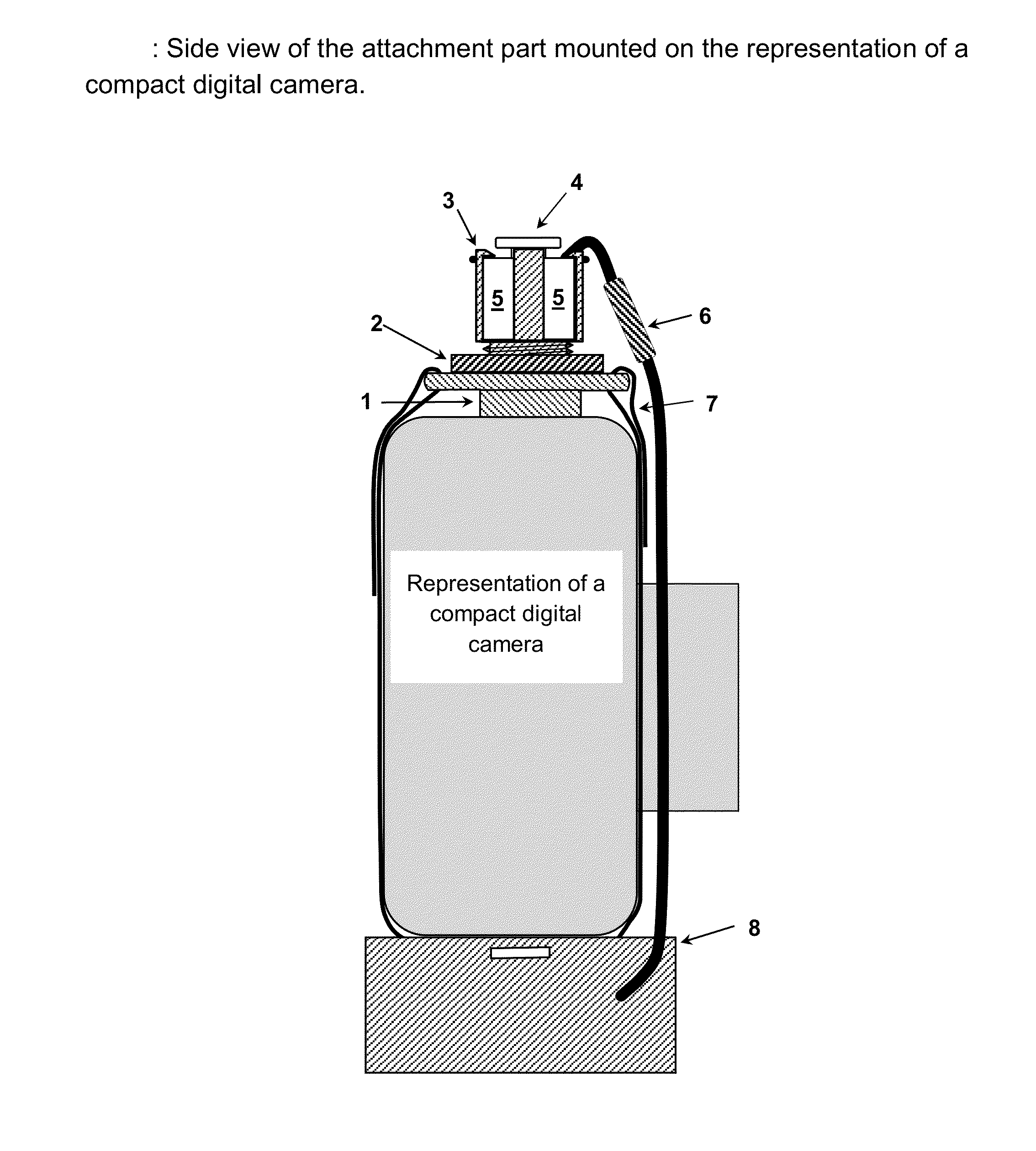
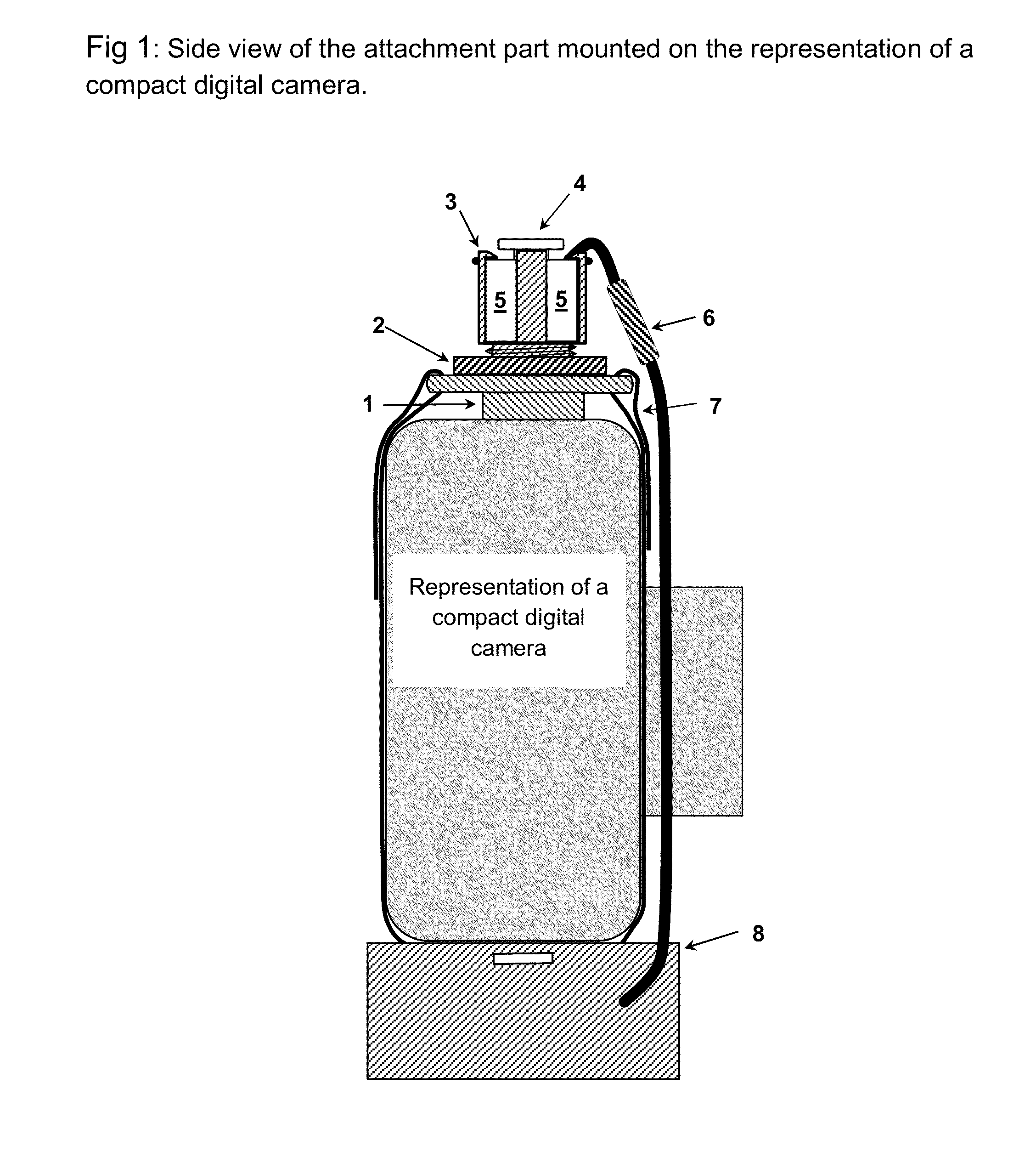
[0011]The four button, key fob type remote controller will command the attachment part, shown in FIG. 1, to perform the required functions using radio frequency communications and appropriate instruction coding.

[0012]Four button remote controller enclosures are readily available and exist in many forms; the design of this part and the design of the radio frequency communication transmitter and receiver are therefore to be left to those skilled in the art such that a low cost, commercially available remote controller may be employed.

[0013]Functions programmed to the remote controller buttons.

[0014]There are three distinct modes in which the remote controller may be employed; commissioning the attachment part, programming the attachment part to operate a particular piece of image capt...

embodiment 2

[0047]This embodiment is specifically designed for image capturing equipment with touch screen control.

[0048]Remote Controller.

[0049]The remote controller for embodiment 2 may be the same 4 button enclosure as in embodiment 1. However the focus force function may not be required.

[0050]Attachment part.

[0051]Please refer to FIGS. 5A and 5B. The attachment assembly 1 to 5 detailed in embodiment 1 can be used for embodiment 2 along with the enclosure 8 and attachment means 7. The forces required to operate a touch screen device are much less than those required to operate a push button. It is therefore envisaged that the actuator assembly will be smaller than that in embodiment 1. FIG. 5B shows how the invention will attach to and support a mobile telephone with integrated image capturing equipment. Since the camera mount, 1, is made from insulating material it will have no effect on capacitive touch screen devices and can therefore sit on the screen. For other types of touch screen dev...


PUM


Abstract

Disclosed herein is a device that may be attached to image capturing equipment. It will act upon the existing manual shutter release means, allowing images to be captured by radio remote control. It will not permanently change the form, fit, or function of said equipment. Normal manual operation of the equipment will still be possible with the invention attached as disclosed. Using remote control, the device will apply programmable forces to existing shutter release means such that the equipment can set photo-metric data and capture images.Its primary purpose is to effectively perform the functions of the finger of the operator such that an operator wishing to capture an image can be distant from the photographic equipment whilst doing so.

Description

BACKGROUND TO THE INVENTION[0001]As well as the limitation of not being able to effectively capture one's own image without assistance this device overcomes several other problems with manually operated image capturing equipment, the following are three examples;[0002]There is often a desire to be able to capture an image whilst the operator is engaged in an activity, for instance whilst hunting.[0003]There are advantages and equipment cost savings when photographing wildlife if the equipment can be placed dose to the subject whilst the operator is some distance from it.[0004]If a camera is mounted on a spotting scope (called digi-scoping), manually depressing the shutter release causes shaking of the equipment resulting in poor image quality. To overcome this problem very expensive equipment is usually necessary. This invention allows standard low cost equipment to be effective, since it nearly eliminates the shaking.[0005]The primary purpose of this invention is to apply, to the s...

Claims


Application Information

Patent Timeline
Patent Type & Authority Applications(United States)
IPC IPC(8): H04N5/232
CPCH04N5/23203G03B17/38G03B17/566G03B17/56H04N23/66
Inventor MARSHALL, PAUL STEPHEN
Owner MARSHALL PAUL STEPHEN
Learn More