
Card edge connector with an improved housing

a card edge connector and a housing technology, applied in the direction of coupling device connection, coupling device two-part connection, coupling/disengagement of coupling parts, etc., can solve the problems of poor contact or dislocation between the contacts and gold fingers, preventing the electrical card from drafting,

Active Publication Date: 2014-12-25
HON HAI PRECISION IND CO LTD
View PDF10 Cites 8 Cited by
  • Summary
  • Abstract
  • Description
  • Claims
  • Application Information

AI Technical Summary

Benefits of technology

The present invention provides a card edge connector that prevents the electrical card from drafting in the elongated direction. The connector has an insulating housing with a recessed passageway and two ladder sections that support the slopes of the electrical card. This improves stability when the card is inserted.

Problems solved by technology

However, it can not prevent the electrical card from drafting in the elongated direction, and a little draft would cause a poor contact or a dislocation between the contacts and the gold fingers, when the gold fingers are highly integrated.

Method used


Image

  • Card edge connector with an improved housing
  • Card edge connector with an improved housing
  • Card edge connector with an improved housing

Examples


Embodiment Construction

[0019]Reference will be made to the drawing figures to describe the present invention in detail, wherein depicted elements are not necessarily shown to scale and wherein like or similar elements are designated by same or similar reference numeral through the several views and same or similar terminology.

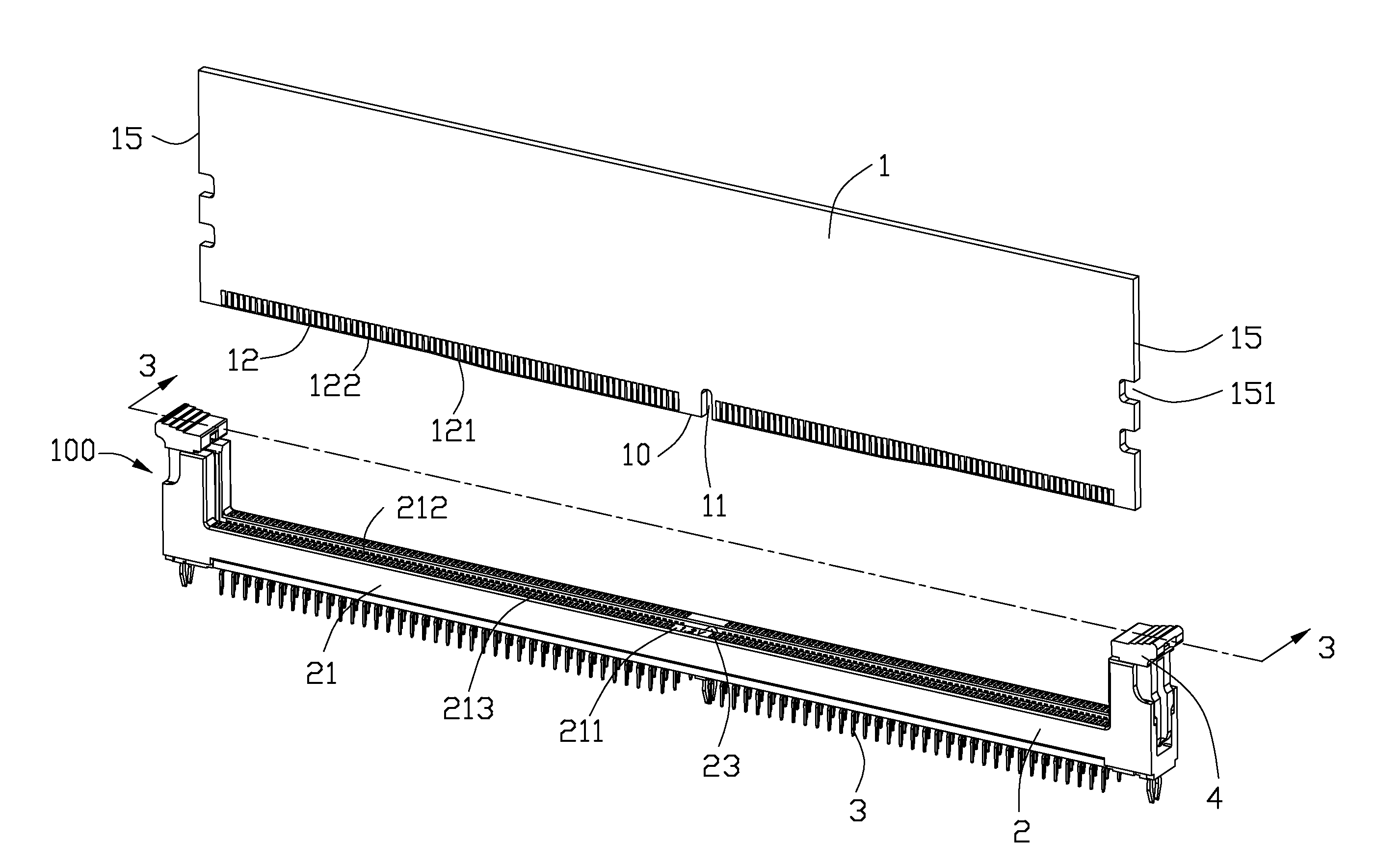
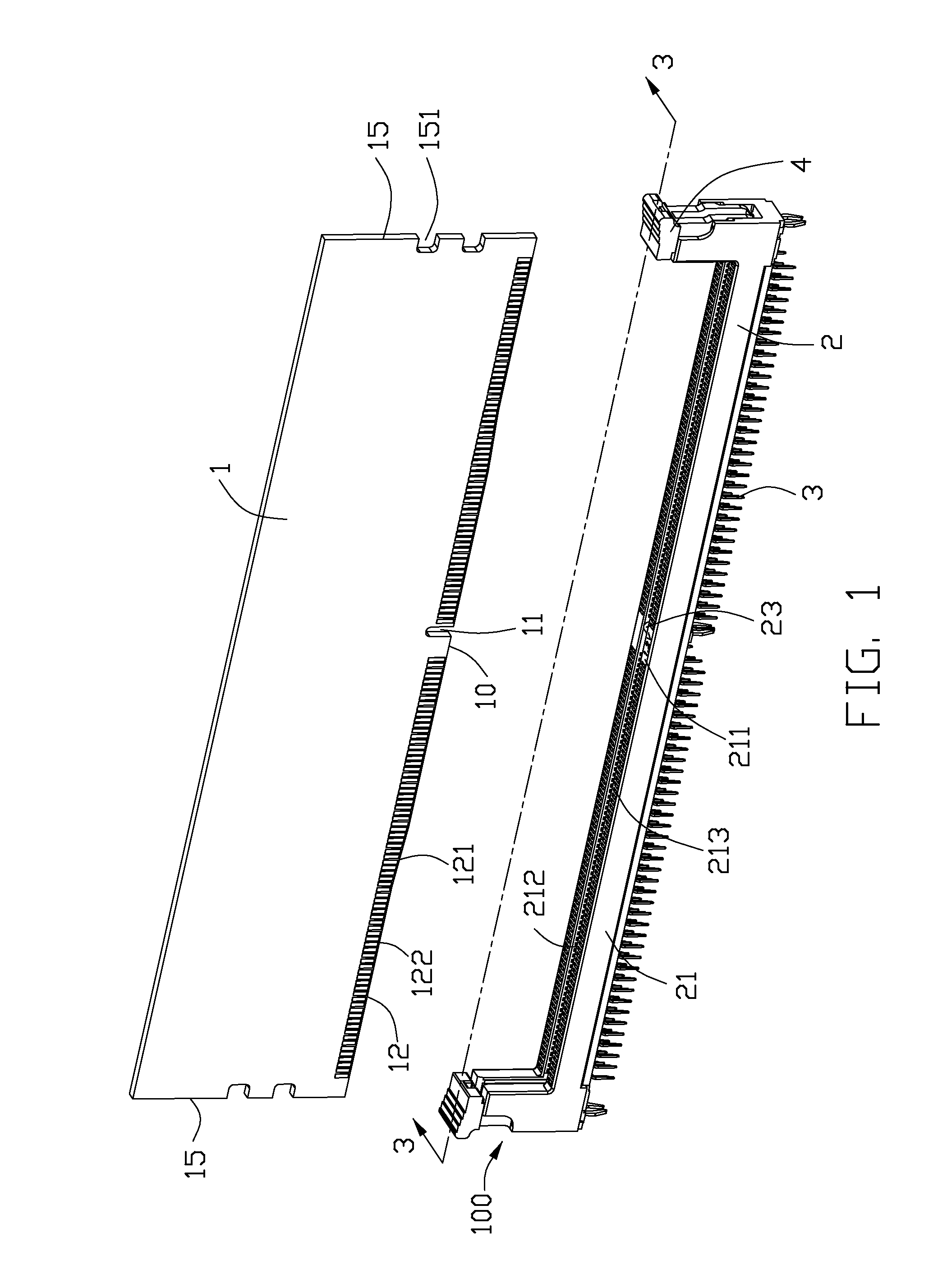
[0020]Referring to FIG. 1, according to the present invention, a card edge connector assembly comprises an electrical card 1 and a card edge connector 100. The electrical card 1 includes a bottom edge 10 and two side edges 15. The electrical card 1 defines at least a notch 11 and a pair of recesses 12, and each of the recesses 12 defines a flat portion 122 and a slope 121 connecting the flat portion 122 with the bottom edge 10.

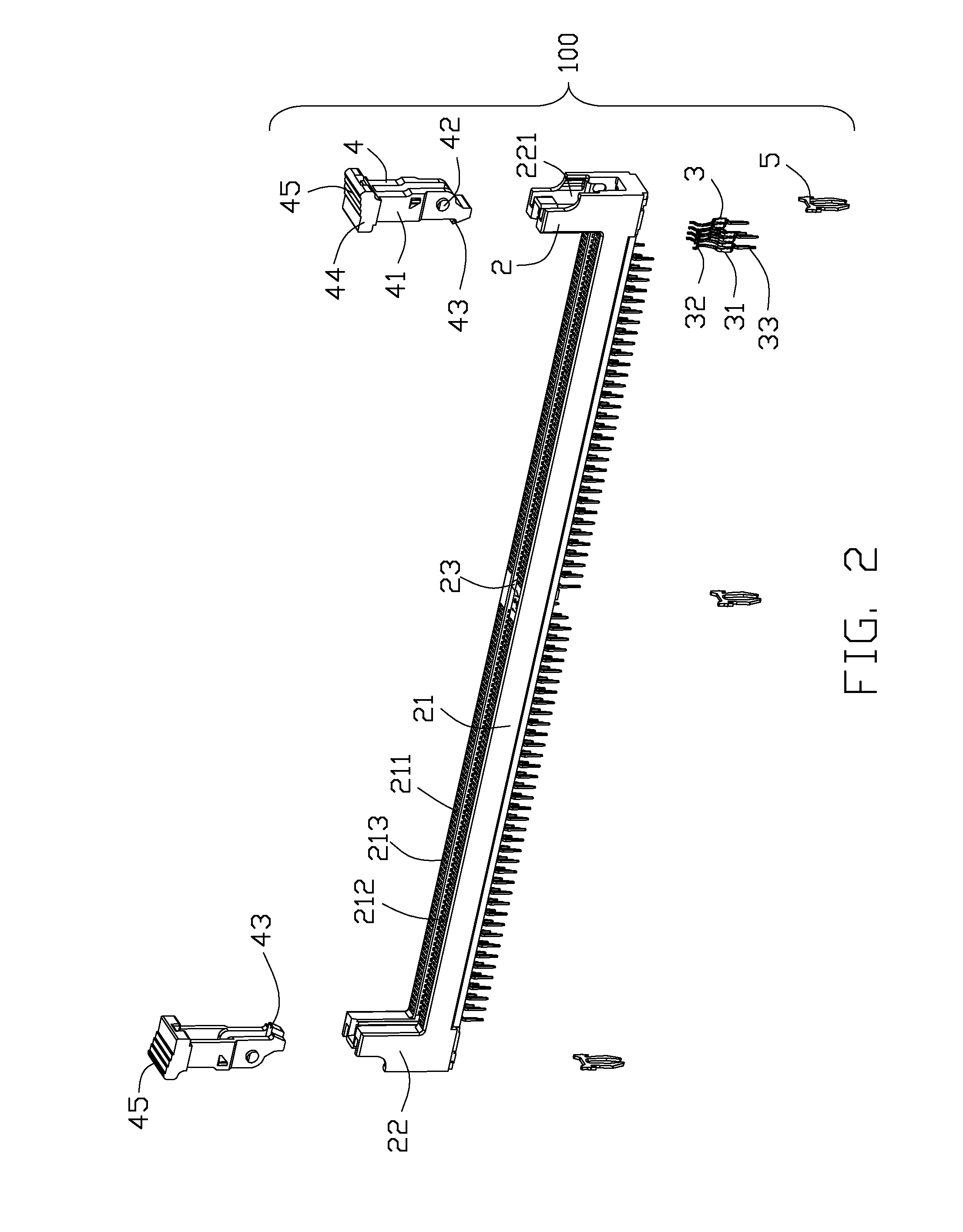
[0021]Referring to FIGS. 2-3, the card edge connector 100 comprises an insulative housing 2, a plurality of contacts 3 retained in the insulative housing 2, a pair of latches 4 disposed at both ends of the insulative housing 2 respectively along the elongated d...


PUM


Abstract

A card edge connector which could be inserted by an electrical card with a pair of slopes in its bottom edge includes an insulating housing and a plurality of contacts retained in the insulating housing. The insulating housing includes a top surface, an elongated passageway which recesses from the top surface, and a pair of ladder sections or protruding portions which protrude into the passageway for supporting the slopes. Therefore, it can enhance the stability when the electrical card is inserted into the passageway.

Description

BACKGROUND OF THE INVENTION[0001]1. Field of the Invention[0002]The present invention relates to card edge connector, more particularly to a card edge connector with an improved housing.[0003]2. Description of Related Art[0004]China Patent No. 202759077, published on Feb. 27, 2013, discloses a related card edge connector for mating an electrical card, and the electrical card defines at least a notch and a recess. The card edge connector defines an elongated slot downwardly, and the slot defines a key corresponding to the notch. The bottom of the slot defines at least a convex corresponding to the recess and the convex locates at the end of the slot in the elongated direction. When the electrical card is inserted in the slot, the convex gets into the recess and supports the electrical card for preventing the electrical card from skewing.[0005]However, it can not prevent the electrical card from drafting in the elongated direction, and a little draft would cause a poor contact or a di...

Claims


Application Information

Patent Timeline
Patent Type & Authority Applications(United States)
IPC IPC(8): H01R13/629
CPCH01R13/62988H01R12/7029H01R12/721
Inventor TANG, WEN-JUNBU, XUE-WUFENG, XIAN-WEI
Owner HON HAI PRECISION IND CO LTD
Learn More