Parking brake lever system

a technology of brake levers and brake levers, which is applied in the direction of brake systems, shafts, aircraft transmission means, etc., can solve the problems of not being able to have a conventional parking brake lever system, and achieve the effects of preventing draft, optimal adaptation, and preventing incommodation

Inactive Publication Date: 2011-08-02
FICO CABLES
View PDF20 Cites 1 Cited by
  • Summary
  • Abstract
  • Description
  • Claims
  • Application Information

AI Technical Summary

Benefits of technology

[0009]The special kinematic arrangement of the actuation lever with respect to the pivotably supported rotation arm leads to a particular actuation kinematics. For the tightening of a parking brake, the hand grip of the parking brake lever system according to the invention can be manually actuated by means of a movement, which is combined of an axial movement and a pivoting movement. Therefore, on the one hand a particularly harmonic and ergonomic way of actuation results, in that the user does not have to unnaturally bend its wrist. On the other hand such a parking brake lever system can particularly preferred be arranged at the dashboard or center console of a motor vehicle, due to its compact construction. A long actuation lever, as used in conventional parking brake is not necessary. Therefore, particular design possibilities result, which would not be possible having a conventional parking brake lever system.
[0023]Preferably, the parking brake lever system further comprises at least one cover element for passing through the at least one actuation lever into the passenger compartment of the vehicle. To this end the cover element comprises a support frame, which is rigidly mounted at the vehicle, and a slide element, which is displaceably supported within the support frame, wherein the actuation lever extends through the slide element. The cover element is integrated into the interior lining and provides a tight and optical pleasing passageway for the actuation levers. Further, it acts for the acoustic insulation and prevents draft. Due to the displaceable support of the slide element within the support frame, the cover element is nearly wear resistant and optimally adapted to the movement of the actuation lever.

Problems solved by technology

Therefore, particular design possibilities result, which would not be possible having a conventional parking brake lever system.

Method used


Image

  • Parking brake lever system
  • Parking brake lever system
  • Parking brake lever system

Examples


Embodiment Construction

[0043]In the following preferred embodiments of the invention are described by reference to the accompanying drawings.

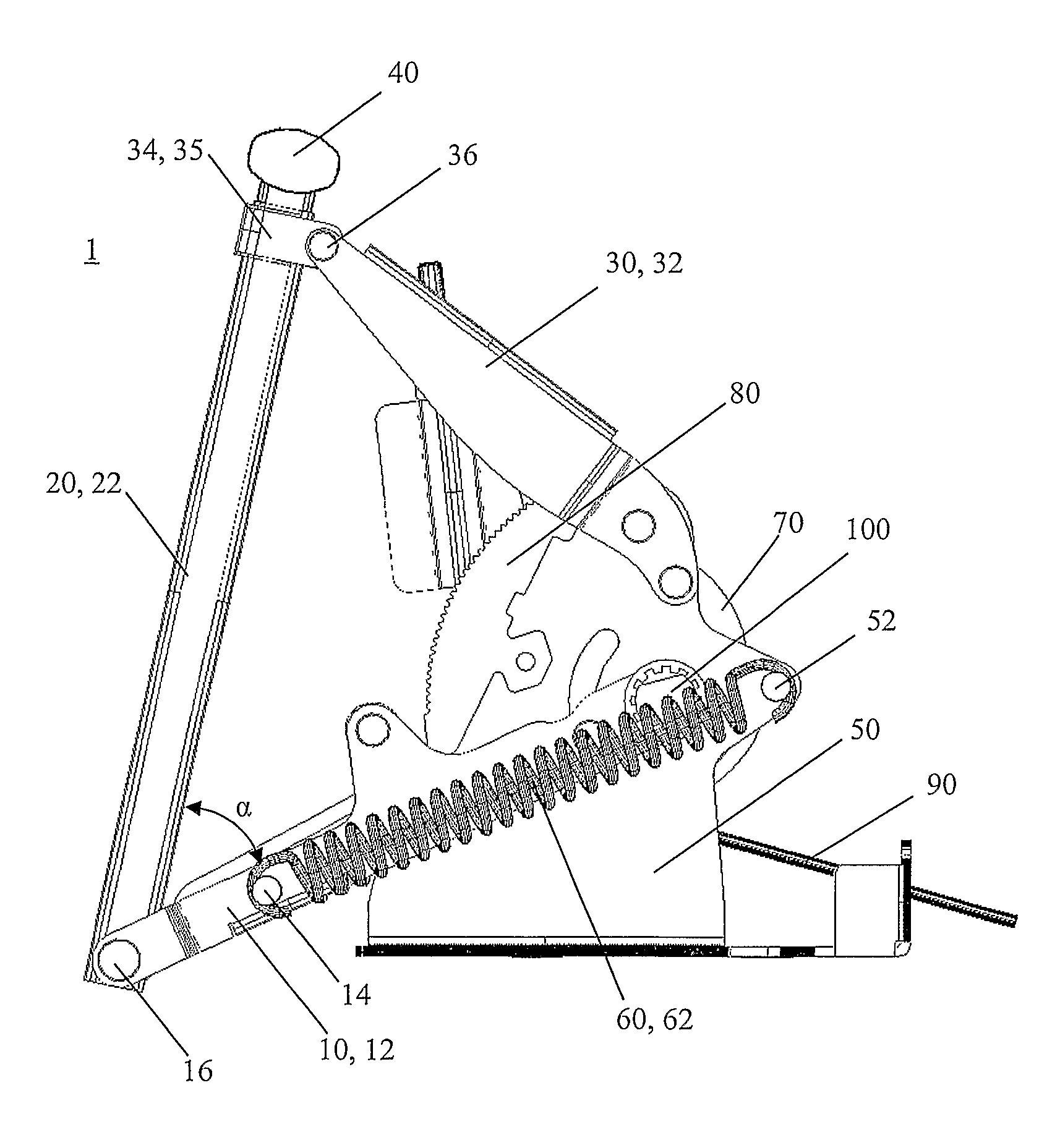
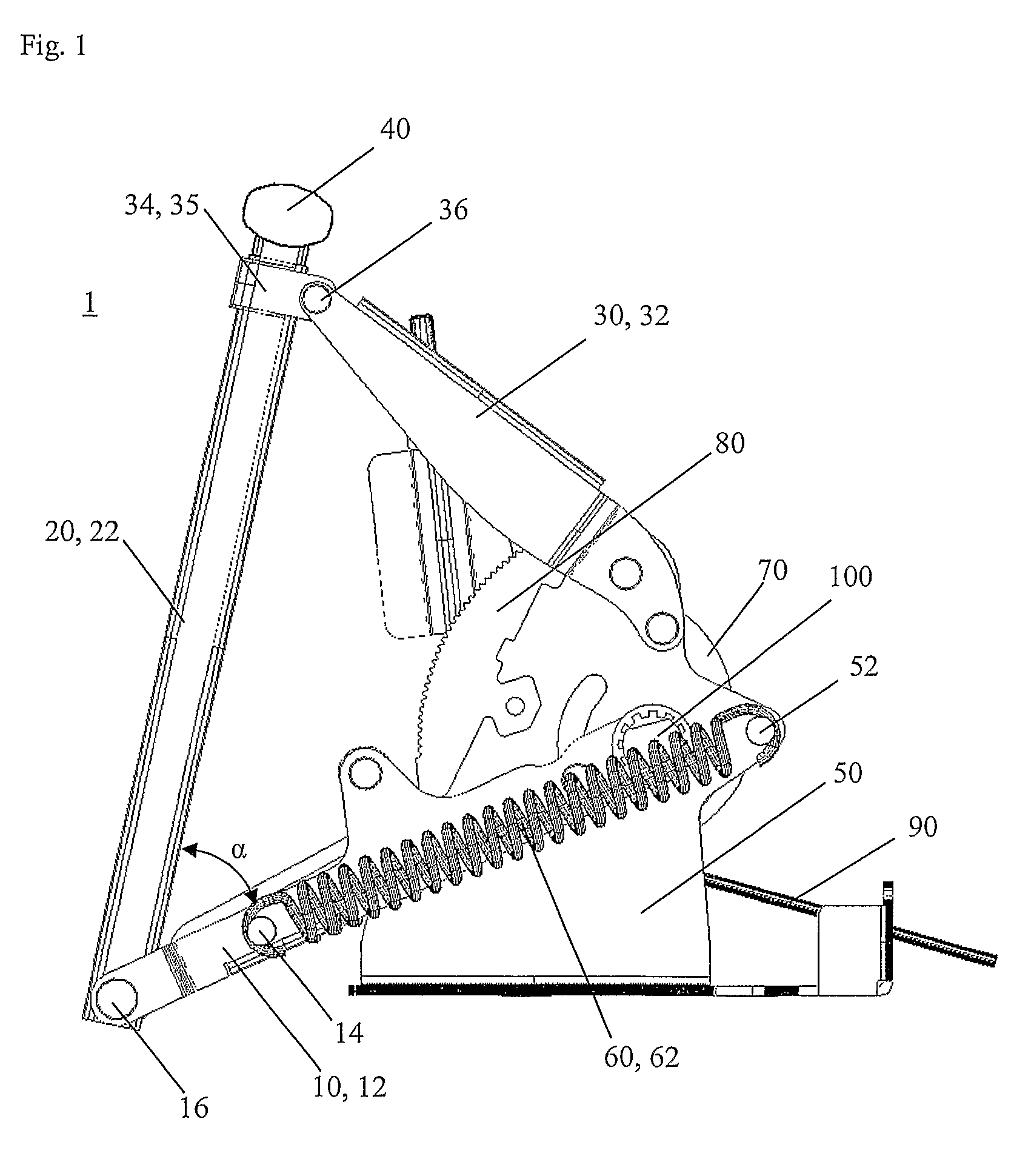
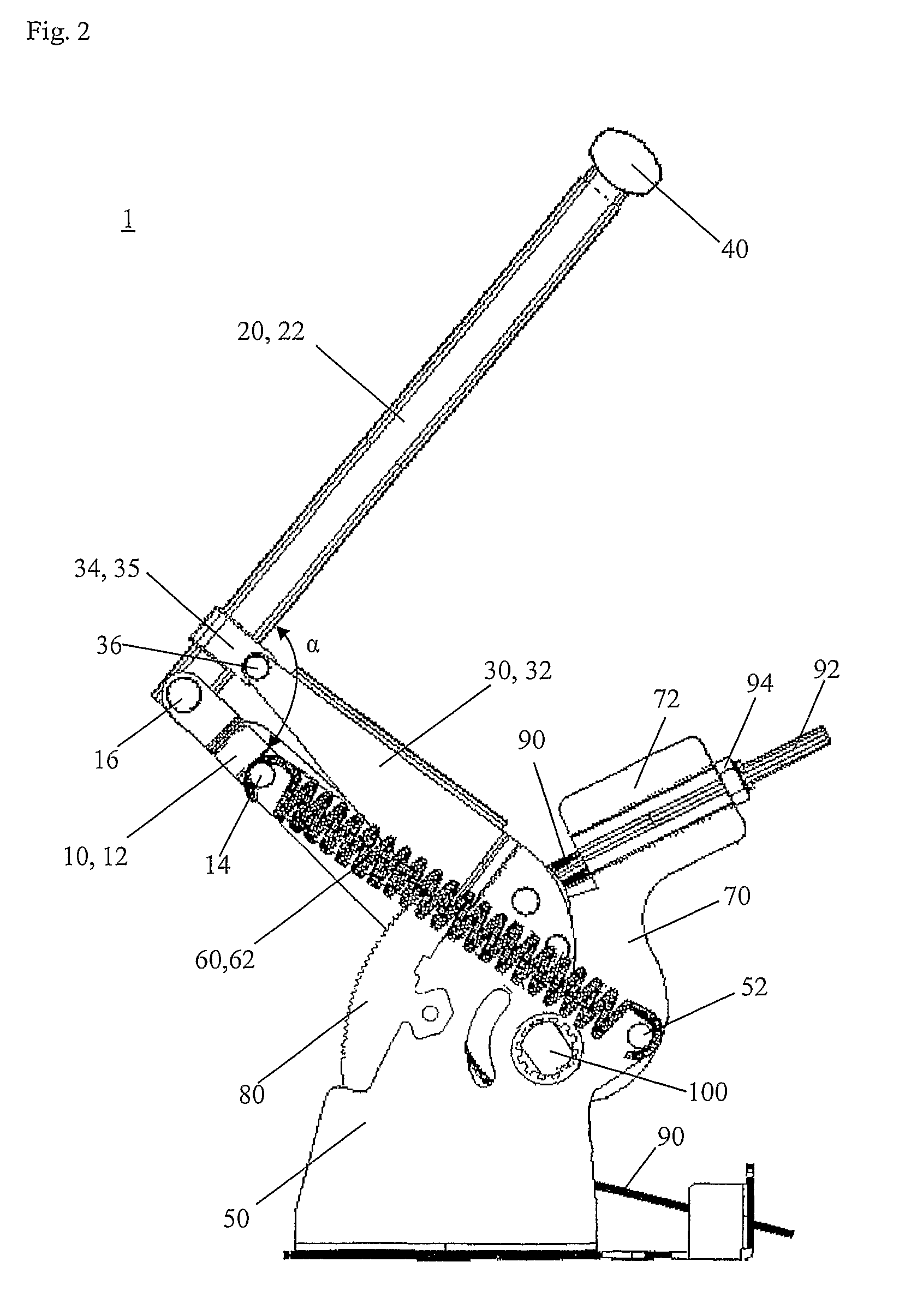
[0044]In FIGS. 1 and 2 a first preferred embodiment of a parking brake lever system 1 is shown. FIG. 1 shows a parking brake lever system 1 in unactuated condition; that means that brake cable 90 is not tightened and a brake connected thereto is not actuated. FIG. 2 shows the same embodiment of parking brake lever system 1 of FIG. 1 in actuated condition. In this condition the brake cable 90 is tightened and the brakes connected thereto (not shown) are actuated.

[0045]The parking brake lever system 1 comprises a fixed support 50, preferably of sheet metal, which is suitably connected to the vehicle. A rotation axis 100 is rotatably supported within support 50. The rotation axis 100 is rigidly connected with a rotation arm 10, 12 and with a cable guiding 70.

[0046]The rotation arm 10, 12 is rotatably connected directly to the support 50 and a rotation movement of the ro...


PUM


Abstract

The present invention relates to parking brake lever system 1 for manually tightening and releasing of at least one brake cable 90, wherein the parking brake lever system 1 comprises at least one rotation arm 10, 12 pivotably supported at a fixed support 50, wherein the rotation arm 10, 12 is connected to the brake cable 90, and at least one actuation lever 20, 22, which at a first end thereof is pivotably connected to the rotation arm 10, 12 and which at a second end thereof is rigidly connected to a hand grip 40, wherein the actuation lever 20, 22 is slidingly supported at the fixed support 50, such that the hand grip 40 defines a curved path during actuation of the parking brake lever system 1.

Description

1. TECHNICAL FIELD[0001]The present invention relates to a parking brake lever system for the actuation of a parking brake, particularly of a parking brake for motor vehicles, wherein the parking brake lever system is manually actuated.2. PRIOR ART[0002]In the prior art different possibilities are disclosed to tighten a parking brake. Parking brakes in motor vehicles in general act on the rear wheels of the vehicle and are actuated via brake cables. For tightening of the brake cable either a parking brake lever or a foot pedal is used. Usually parking brake levers are mounted at the middle tunnel of the motor vehicle between the front seats.[0003]During design and ergonomic considerations, however, other positions in a motor vehicle are conceivable. So, it can for example be desirable to integrate a parking brake lever in the dashboard or center console of a motor vehicle. So, for example the EP 1 205 368 A2 shows a parking brake lever which is integrated in the center console of a ...

Claims


Application Information

Patent Timeline
Patent Type & Authority Patents(United States)
IPC IPC(8): F16D65/30B60T7/10F16D65/28
CPCB60T7/101Y10T74/20408Y10T74/20426
Inventor VIDAL FERRER, GUILLEMPRAT TERRADES, JAUMEJORNET VIDAL, JORDI
Owner FICO CABLES
Why Eureka
Try Eureka