Dynamic Predictor for Articulated Mechanisms

a technology of dynamic predictor and articulated mechanism, which is applied in the field of dynamic predictor, can solve problems such as problems such as problems such as problem solving of differential equations by term expansion, and achieve the effect of improving the control of articulated mechanism

Active Publication Date: 2015-01-01
WISCONSIN ALUMNI RES FOUND
View PDF3 Cites 21 Cited by
  • Summary
  • Abstract
  • Description
  • Claims
  • Application Information

AI Technical Summary

Benefits of technology

[0009]Generally, the dynamic predictor performs an analysis of the motion of the system by evaluating solutions of the differential equation model in incremental time steps. The state variables of the differential equation constitute those quantities for which at a given moment in time, any other quantity in the system is related through an algebraic formula. Each time-step interval of the motion trajectory is approximated by a collection of polynomials, one polynomial for each state variable to express continuous variation in that variable over the duration of the time step. Each polynomial has “free parameter” coefficients relating to the constraints of the differential equation model to be applied at the endpoint of the step. These free parameters are not evaluated directly from the differential equation (for example, by series expansion about the start point of the step) but instead by a minimization of “the residuals”. These residuals are derived from the difference between the derivative of a polynomial determined directly from its coefficients and the same quantity evaluated by substituting the collection of polynomials into the differential equation. Expanding the residuals using Taylor series, the residuals along with multiple orders of their derivatives are readily calculated from the Taylor series coefficients, anywhere on the time-step interval including the endpoint, and an algorithmic differentiation procedure determines the sensitivity of the Taylor coefficients to changes in the free parameters. This procedure allows the automatic adjustment of the polynomial free parameters to minimize the residuals and their derivatives at the time step endpoint. For conditions at the end of the time step to be controlled through adjustment of the free parameters is of special importance in obtaining a stable and accurate solution of a stiff dynamical system. In this way, improved polynomial approximations of the solution for the differential equation are obtained with the computation of a limited number of expansion terms.
[0027]It is thus a feature of at least one embodiment of the invention to provide improved control of articulated mechanisms such as walking machines.

Problems solved by technology

When the articulated mechanism has “stiff” springs, for example rubber bushings or other sources of compliance with high spring rates, solving the differential equations by term expansions can prove problematic.

Method used


Image

  • Dynamic Predictor for Articulated Mechanisms
  • Dynamic Predictor for Articulated Mechanisms
  • Dynamic Predictor for Articulated Mechanisms

Examples


Embodiment Construction

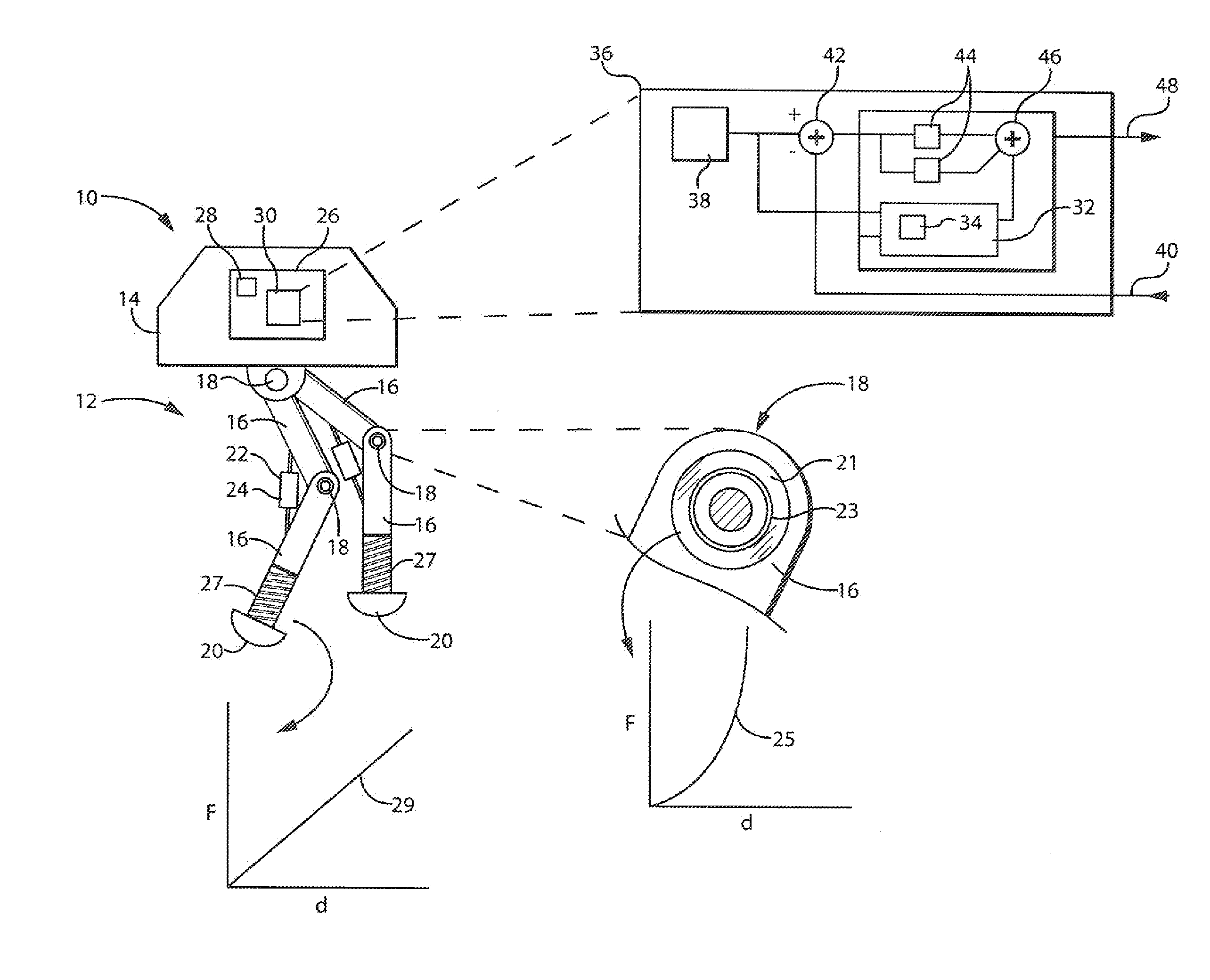
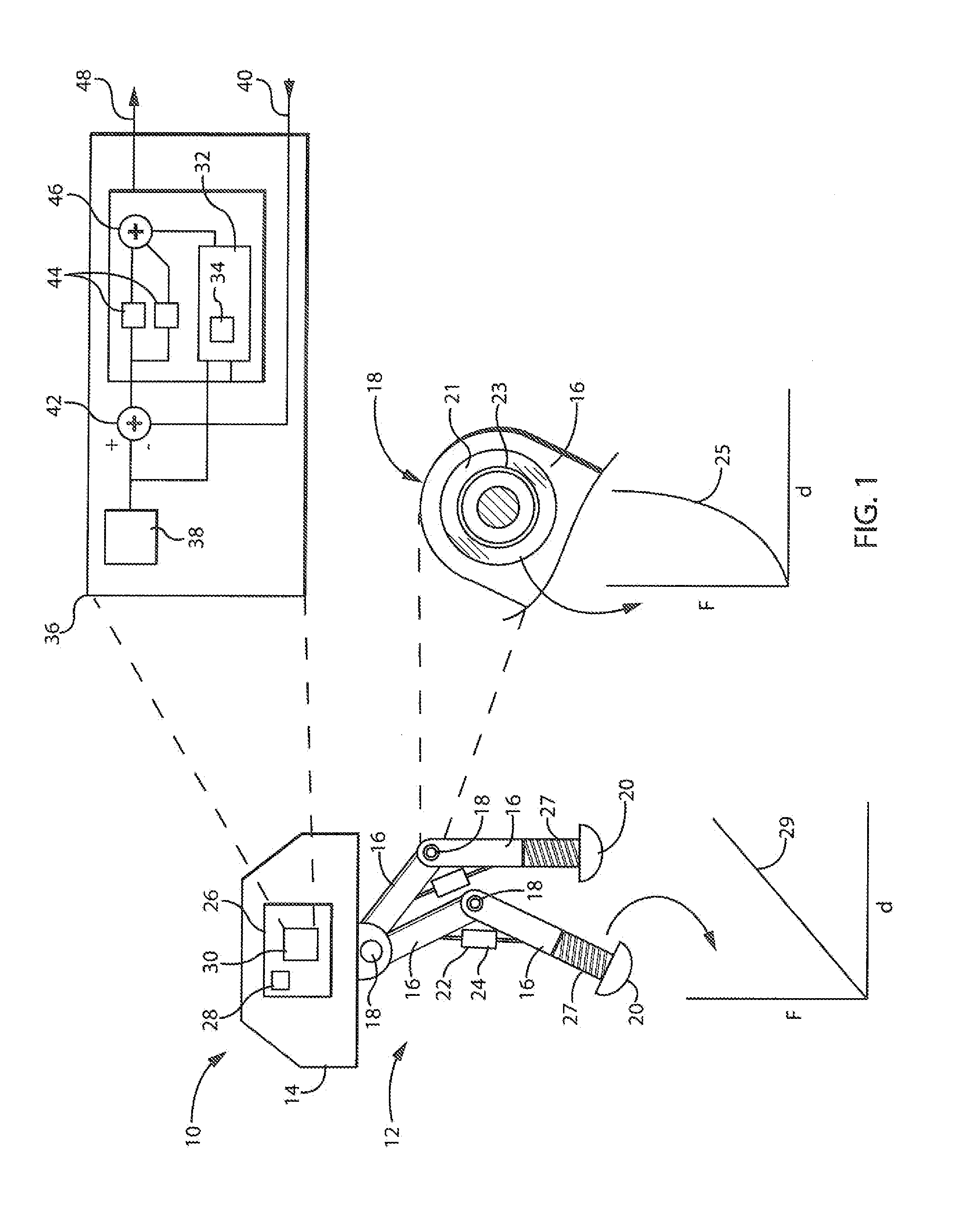
[0031]Referring now to FIG. 1, an articulated controlled dynamical mechanism such as a walking machine 10 may include articulated legs 12 positioned to support a main machine body 14. Each of the articulated legs 12 may include links 16 being substantially rigid bars connected by joints 18. The legs 12 may have an end effector 20, for example, providing for ground-contacting feet or the like.

[0032]Each of the joints 18 provides for relative movement between the associated links 16 using mechanisms including but not limited to a slide or rotary coupling. Each of the joints 18 may communicate with an actuator 22, such as a hydraulic cylinder or motor for moving the joint 18, and a sensor 24, such as an encoder, linear variable transformer (LVT), tachometer, or the like (shown incorporated into the actuator 22), for reading out the position and velocity of the joint 18 when moved.

[0033]Electrical signals to the actuators 22 and from the sensors 24 may be communicated to an electronic c...


PUM


Abstract

A dynamic predictor usable for rapid and accurate calculation of joint commands of an articulated dynamical mechanism describes the relationship between the joints in the form of a differential equation. The predictor solves this differential equation for predicted joint states by fitting a polynomial equation having free parameters describing the predicted joint states to the differential equations by minimizing the differential equation residuals. This minimization employs a series expansion allowing algorithmic differentiation.

Description

STATEMENT REGARDING FEDERALLY SPONSORED RESEARCH OR DEVELOPMENTCross Reference to Related ApplicationBackground of the Invention[0001]The present invention relates to articulated mechanisms, such as but not limited to walking robots, and more particularly to a dynamic predictor for determining link positions along with displacements of multiple joints achieving those positions, being particularly useful when selected joints have relatively stiff springs such as bushings or other provisions for compliance in their attachment to adjoining links.[0002]Articulated mechanisms such as walking robots or robot arms can be understood as a set of rigid links connected to each other by joints. The joints in these mechanisms may be associated with actuators such as motors to displace the joints directly or to apply forces effecting displacement of the joints, “passive” springs and dampers, along with sensors providing an indication of joint position. Common joints include so-called revolute joi...

Claims


Application Information

Patent Timeline
Patent Type & Authority Applications(United States)
IPC IPC(8): B25J9/16
CPCY10S901/02B25J9/1656B62D57/032B25J9/163
Inventor MILENKOVIC, PAUL, H.
Owner WISCONSIN ALUMNI RES FOUND
Why Eureka
Try Eureka