Mask for deposition

Active Publication Date: 2015-01-08
SAMSUNG DISPLAY CO LTD
View PDF2 Cites 35 Cited by
  • Summary
  • Abstract
  • Description
  • Claims
  • Application Information

AI Technical Summary

Benefits of technology

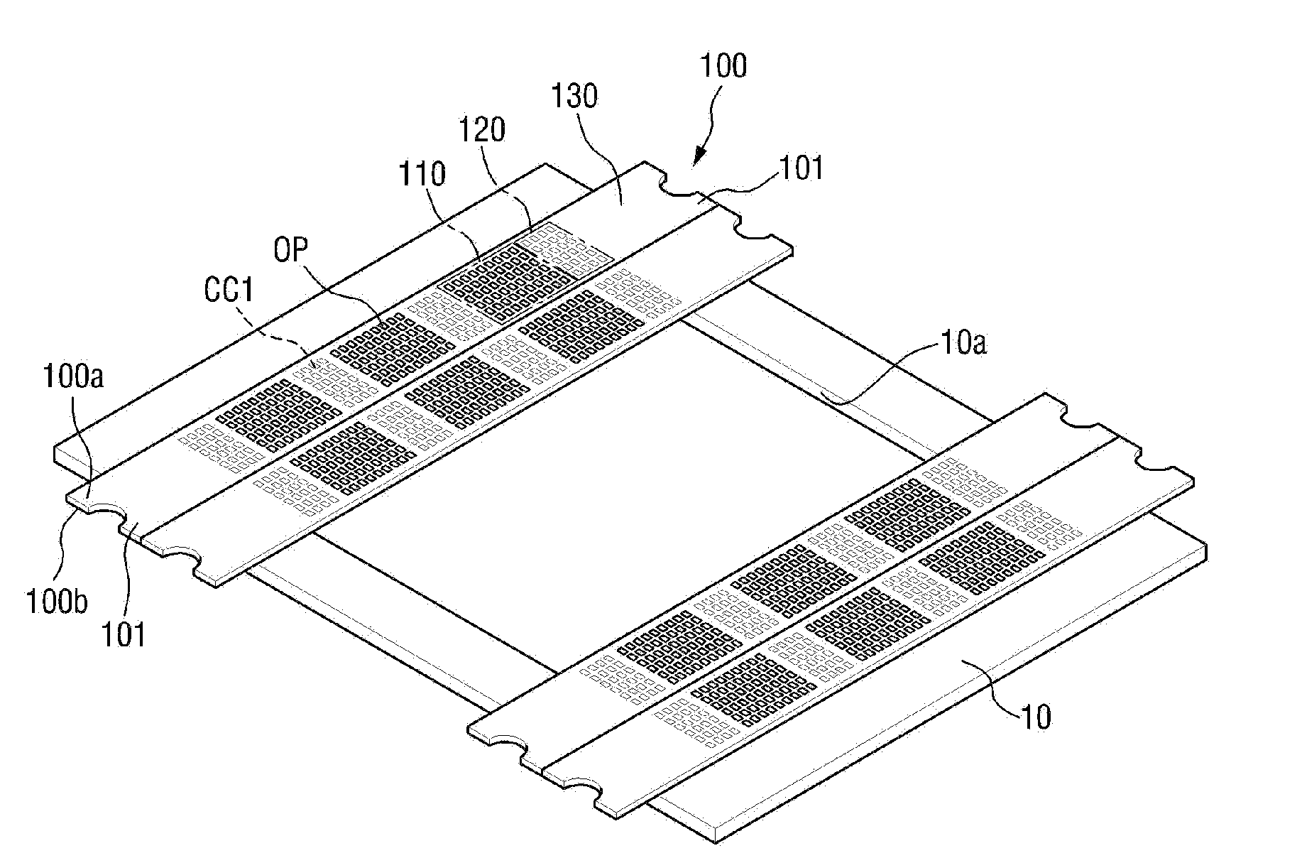
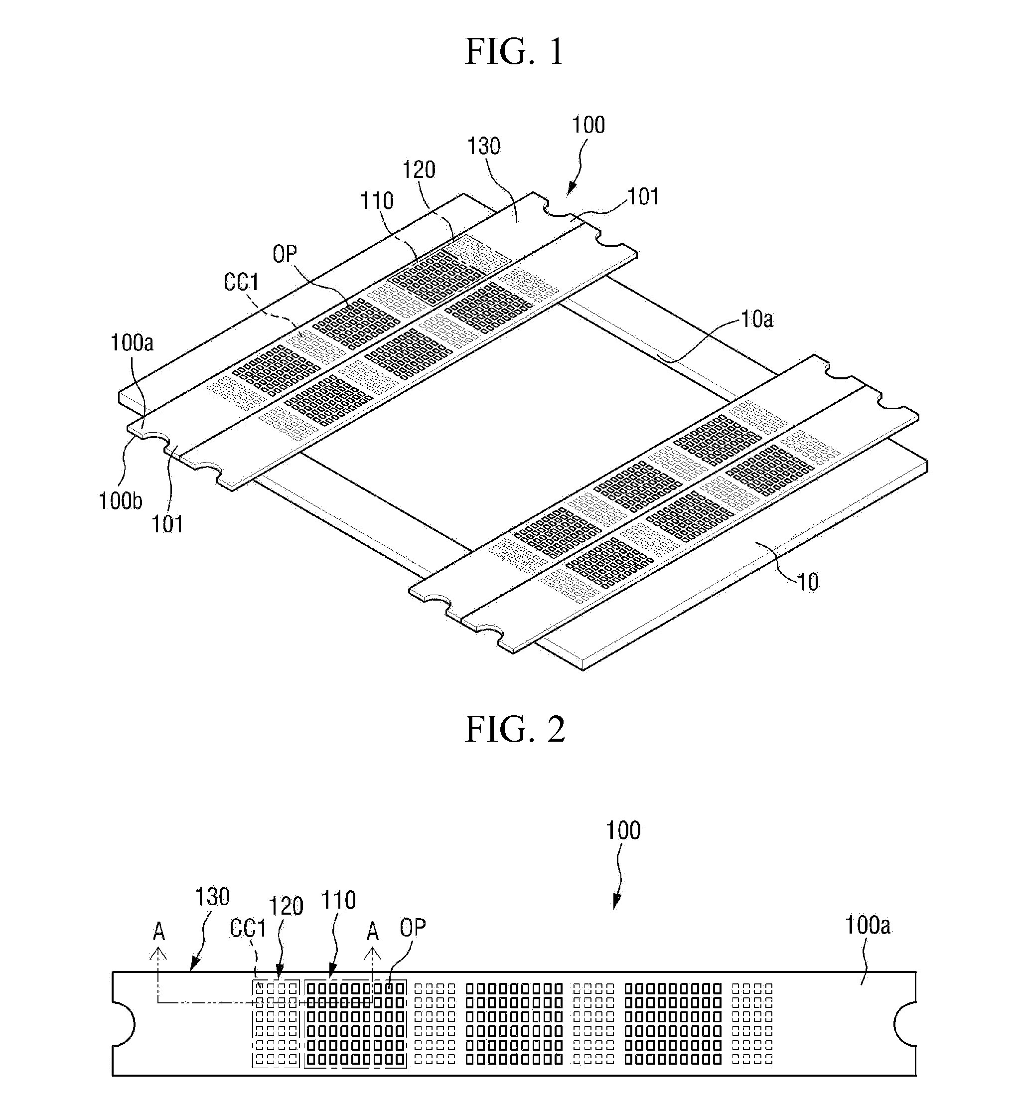
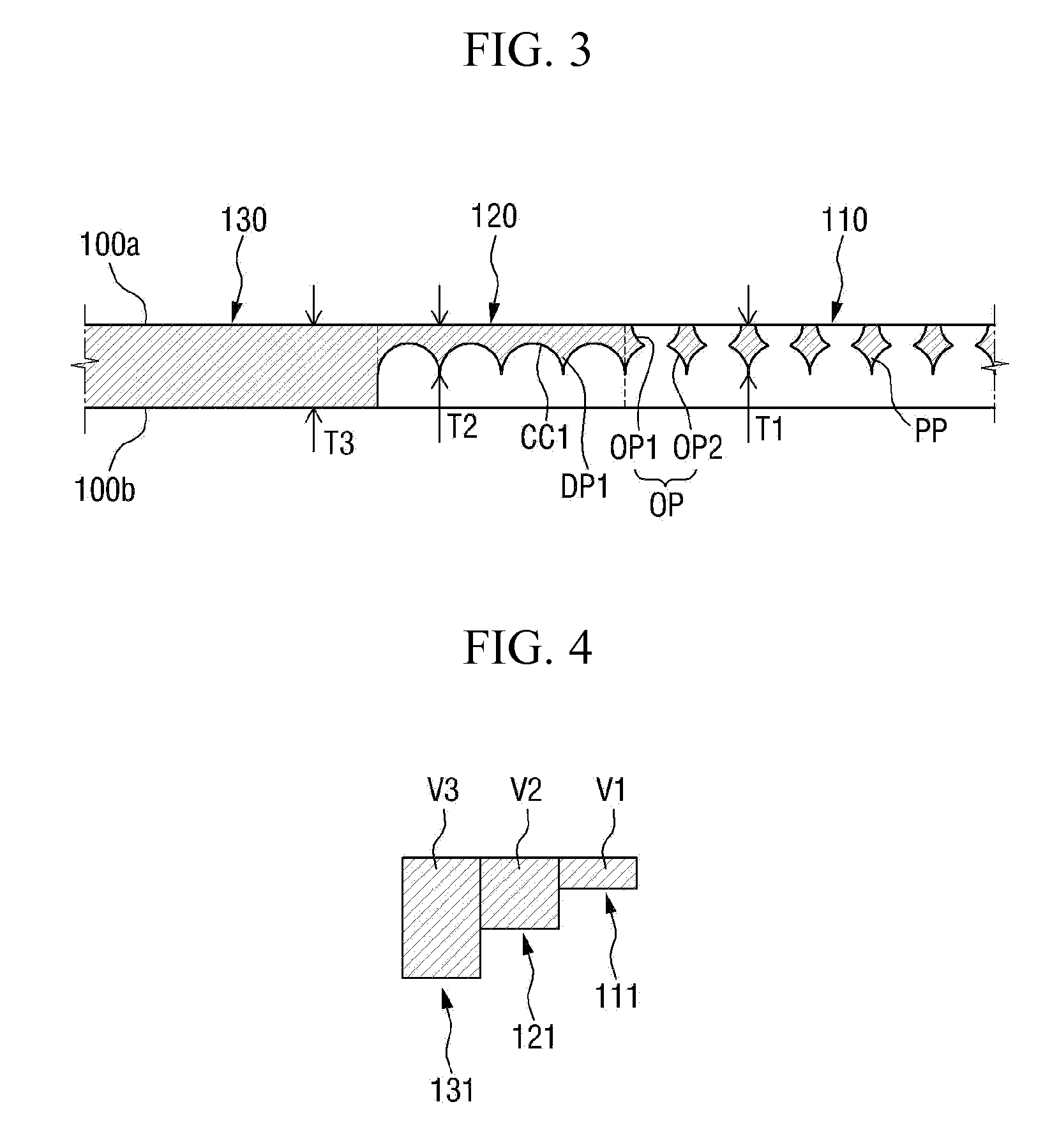
The invention provides a mask for deposition that reduces defects in thin film deposition by improving adhesion between the mask and the substrate to minimize the shadow phenomenon. The mask has a unique design with a gradual change in volume from the deposition pattern part to the fixing part, which prevents sudden volume changes that can cause wrinkling or lifting between the mask and substrate. This decreases the likelihood of thin film deposition defects and ensures a more uniform deposition pattern.

Problems solved by technology

Accordingly, a thin film deposition defect of the substrate may be generated.

Method used


Image

  • Mask for deposition
  • Mask for deposition
  • Mask for deposition

Examples


Embodiment Construction

[0032]Advantages and features of the invention and methods of accomplishing the same may be understood more readily by reference to the following detailed description of embodiments and the accompanying drawings. The invention may, however, be embodied in many different forms and should not be construed as being limited to the embodiments set forth herein. Rather, these embodiments are provided so that this disclosure will be thorough and complete and will fully convey the invention to those skilled in the art, and the invention will only be defined by the appended claims.

[0033]It will also be understood that when a layer is referred to as being “on” another layer or substrate, it can be directly on the other layer or substrate, or intervening layers may also be present. The same reference numbers indicate the same components throughout the specification. Like numbers refer to like elements throughout. As used herein, the term “and / or” includes any and all combinations of one or mor...


PUM

PropertyMeasurementUnit
Thicknessaaaaaaaaaa
Lengthaaaaaaaaaa
Shapeaaaaaaaaaa

Abstract

A mask for deposition includes a plurality of deposition pattern parts arranged spaced apart from each other in a first direction, and a plurality of pattern openings defined in each deposition pattern part; a plurality of dummy pattern parts disposed at opposing sides of the plurality of deposition pattern parts in the first direction, respectively, and a plurality of recesses defined in each dummy pattern part; and a plurality of fixing parts respectively disposed at external sides of outermost dummy pattern parts among the plurality of dummy pattern parts, in the first direction. A maximum thickness of the each dummy pattern part is equal to or larger than a maximum thickness of the each deposition pattern part, and is smaller than a maximum thickness of each fixing part.

Description

[0001]This application claims priority to Korean Patent Application No. 10-2013-0079827 filed on Jul. 8, 2013, and all the benefits accruing therefrom under 35 U.S.C. 119, the contents of which in its entirety are herein incorporated by reference.BACKGROUND[0002]1. Field[0003]The invention relates to a mask for deposition.[0004]2. Description of the Prior Art[0005]An organic light emitting diode display among the display devices is a self-emission display device, and has advantages of a wide viewing angle, excellent contrast, and a rapid response speed, thereby attracting attention as a next-generation display device.[0006]The organic light emitting display includes an intermediate layer including at least a light emitting layer, between electrodes facing each other. The electrodes and the intermediate layer may be formed by various methods, and one of the methods is a deposition method.[0007]In order to manufacture the organic light emitting display by the deposition method, a thin...

Claims


Application Information

Patent Timeline
IPC IPC(8): B05C21/00
CPCB05C21/005C23C14/042B05B12/20H10K71/166H05B33/10H10K71/00
Inventor LEE, SANG YUN
Owner SAMSUNG DISPLAY CO LTD
Why Eureka
Try Eureka