Method of manufacturing zinc-coated electrode wire for electric discharge processors using hot dip galvanizing process

Inactive Publication Date: 2006-06-29
PUNG KUK
View PDF5 Cites 18 Cited by
  • Summary
  • Abstract
  • Description
  • Claims
  • Application Information

AI Technical Summary

Benefits of technology

[0022] Therefore, it is an object of the present invention to alleviate the problems encountered in the related art and to provide a method of manufacturing a zinc-coated electrode wire for electro discharge machining by use of a hot dip galvanizing process, by subjecting a wire to the series of processes of firstly surface-forming, pre-coating, main-coating, secondly surface-forming, heat-treating and drawing. The inventive method is advantageous in terms of formation of uniformly coated zinc

Problems solved by technology

However, when the workpiece is continuously machined with the electrode wire while being applied with voltage, the end portion of the wire is exhausted and thus such a wire cannot be reused after electro discharge.
Further, heat generated by electro discharge may cause breakage of the electrode wire.
Use of such a brass wire leads to improvement of electro discharge effect, but is restricted by solid-solution limitations of conventional alloys.
Although a copper wire is mainly used as an electrode wire for wire electro discharge machining, it is low in tensile strength.
Hence, high tension cannot be applied to the wire, and it is difficult to restrain vibration of the electrode wire upon electro discharge machining, causing rough machining of the workpiece and easy breakage of the wire.
In addition, workability of electro discharge machining of copper per se is not good and a machining speed becomes slow.
However, the wire is lowered in drawability.
Thus, a drawing process is difficult to perform.
The brass electrode wire on which zinc is coated is manufactured by various processes, for example, electroplating, hot dip galvanizing, plasma coating and thermal spraying, in which the plasma coating process and the thermal spraying process are disadvantageous in terms

Method used


Image

  • Method of manufacturing zinc-coated electrode wire for electric discharge processors using hot dip galvanizing process
  • Method of manufacturing zinc-coated electrode wire for electric discharge processors using hot dip galvanizing process
  • Method of manufacturing zinc-coated electrode wire for electric discharge processors using hot dip galvanizing process

Examples


Example

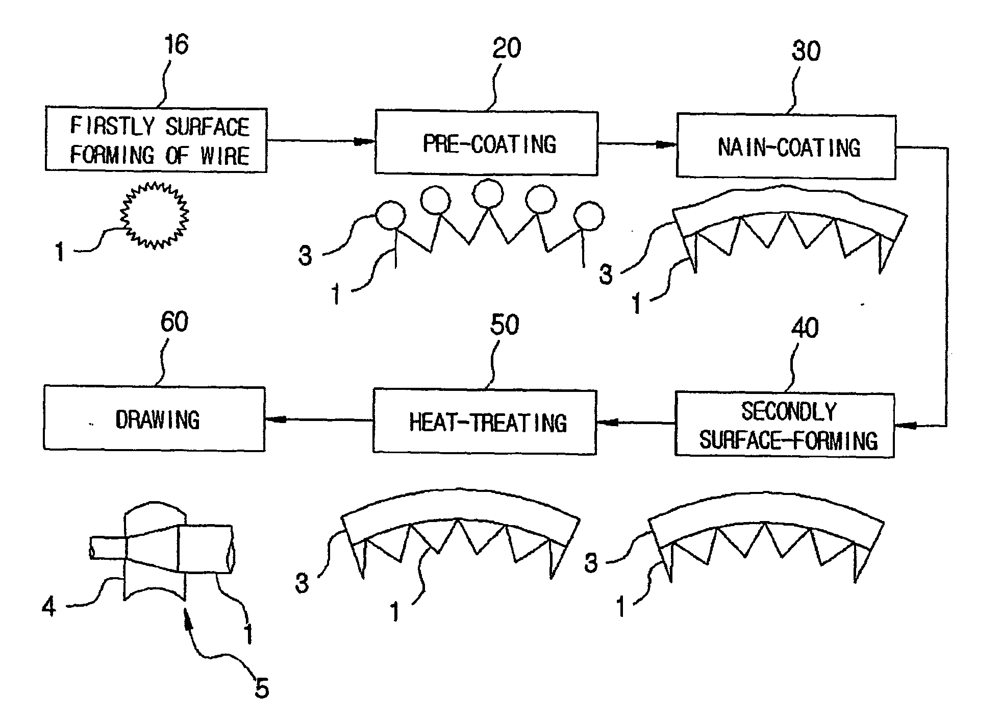
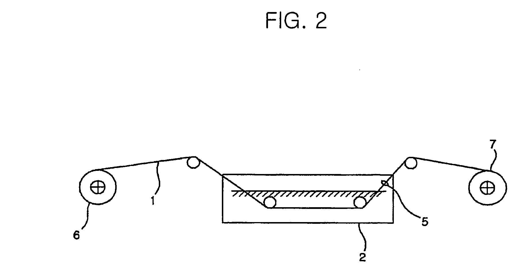
[0034] With reference to FIG. 1, there is illustrated a manufacturing method of a zinc-coated electrode wire for electro discharge machining using a hot dip galvanizing process, according to the present invention. In addition, FIG. 2 schematically illustrates a coating process by use of a molten bath, according to the manufacturing method of the zinc-coated electrode wire for electro discharge machining using a hot dip galvanizing process.

[0035] In the present invention, a specific description for the related techniques or structures is considered to be unnecessary and thus is omitted.

[0036] Further, before the manufacturing method of the present invention is disclosed, it should be understood that the terminology used therein is for the purpose of describing particular embodiments only and is not intended to be limiting.

[0037] As shown in FIG. 1, a wire 1 is firstly surface-processed in such a way that its terminal end is tapered while the wire 1 is drawn through a first die, at...


PUM

PropertyMeasurementUnit
Temperatureaaaaaaaaaa

Abstract

Disclosed is a method of manufacturing a zinc-coated electrode wire for electro discharge machining using a hot dip galvanizing process. The method includes firstly surface-forming a wire (1) in such a way that its terminal end is tapered while the wire is drawn through a first die at step 10, pre-coating zinc around the firstly processed wire in a molten zinc bath (2) at step 20, main-coating the pre-coated wire with zinc (3) using a sizing die before zinc pre-coated on the wire is hardened at step 30, secondly surface-forming the main-coated wire in such a way that zinc coated around the wire has a uniform thickness using a second die having a smaller diameter than the wire at step 40, heat-treating the secondly surface-processed wire at step 50, and drawing the heat-treated wire using a third die (5) made of natural diamond at step 60.

Description

TECHNICAL FIELD [0001] The present invention relates to methods of manufacturing an electrode wire, which is useful as a cutting tool of a workpiece, using a hot dip galvanizing process. More specifically, the present invention is directed to a method of manufacturing a zinc-coated electrode wire for electro discharge machining using a hot dip galvanizing process, by subjecting a wire to the series of processes of firstly surface-forming, pre-coating, main-coating, secondly surface-forming, heat-treating and drawing, which is advantageous in terms of uniformly coating zinc on the wire by the hot dip galvanizing process, and thus reducing manufacturing cost, thereby achieving economic benefits. In addition, environmental contamination by harmful gas and wastewater inevitably generated according to conventional methods can be prevented by the present invention. Further, increase of both of thickness and adhesion of a zinc-coated layer results in decreasing generation of waste powder u...

Claims


Application Information

Patent Timeline
IPC IPC(8): B23H7/08C23C2/02C23C2/06C23C2/26C23C2/28C23C2/38
CPCB23H7/08C23C2/02C23C2/26C23C2/28C23C2/38C23C2/06
Inventor LEE, JONG-CHO
Owner PUNG KUK
Why Eureka
Try Eureka