
System for reducing engine roll

Active Publication Date: 2015-01-08
FORD GLOBAL TECH LLC
View PDF8 Cites 23 Cited by
  • Summary
  • Abstract
  • Description
  • Claims
  • Application Information

AI Technical Summary

Benefits of technology

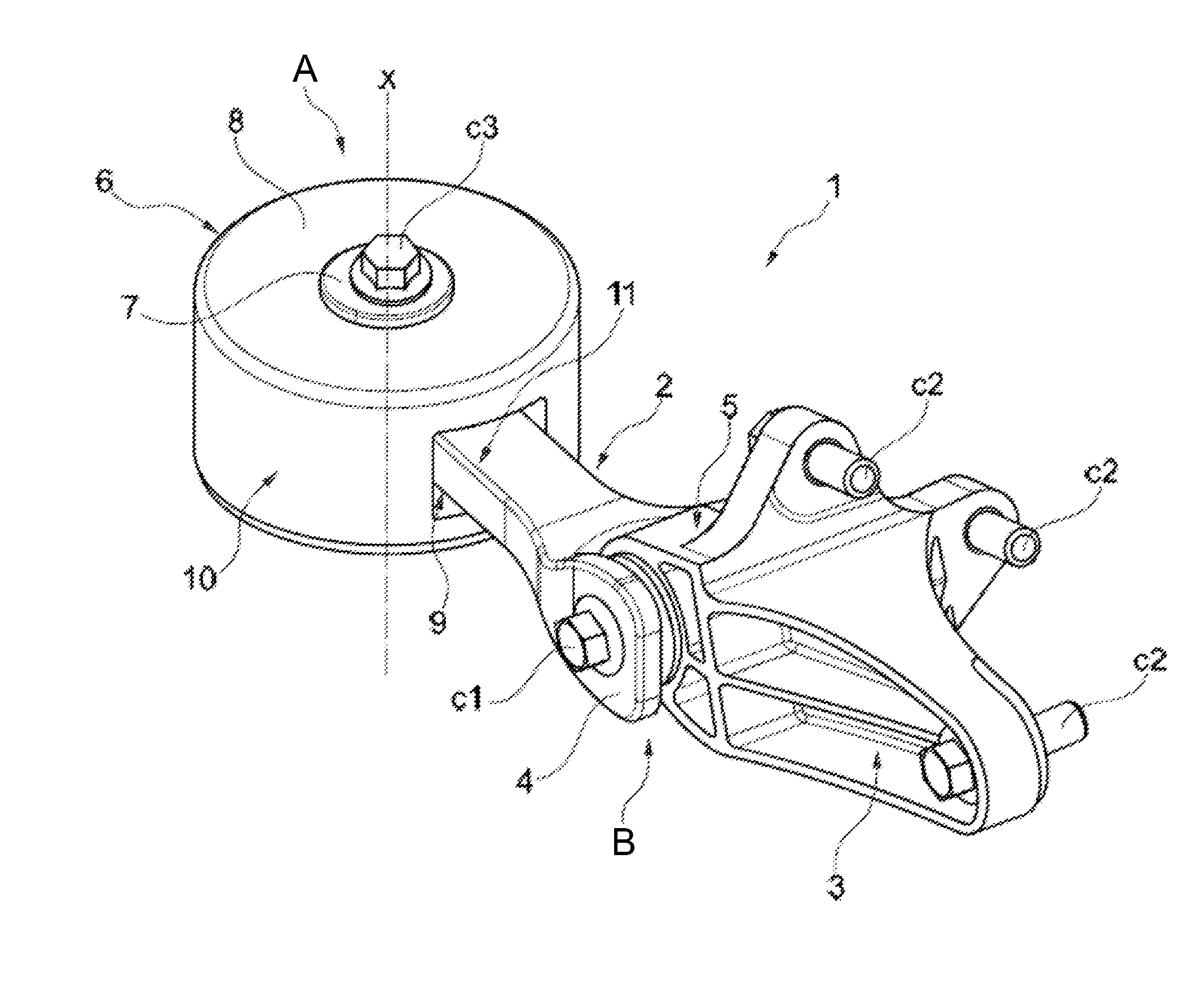
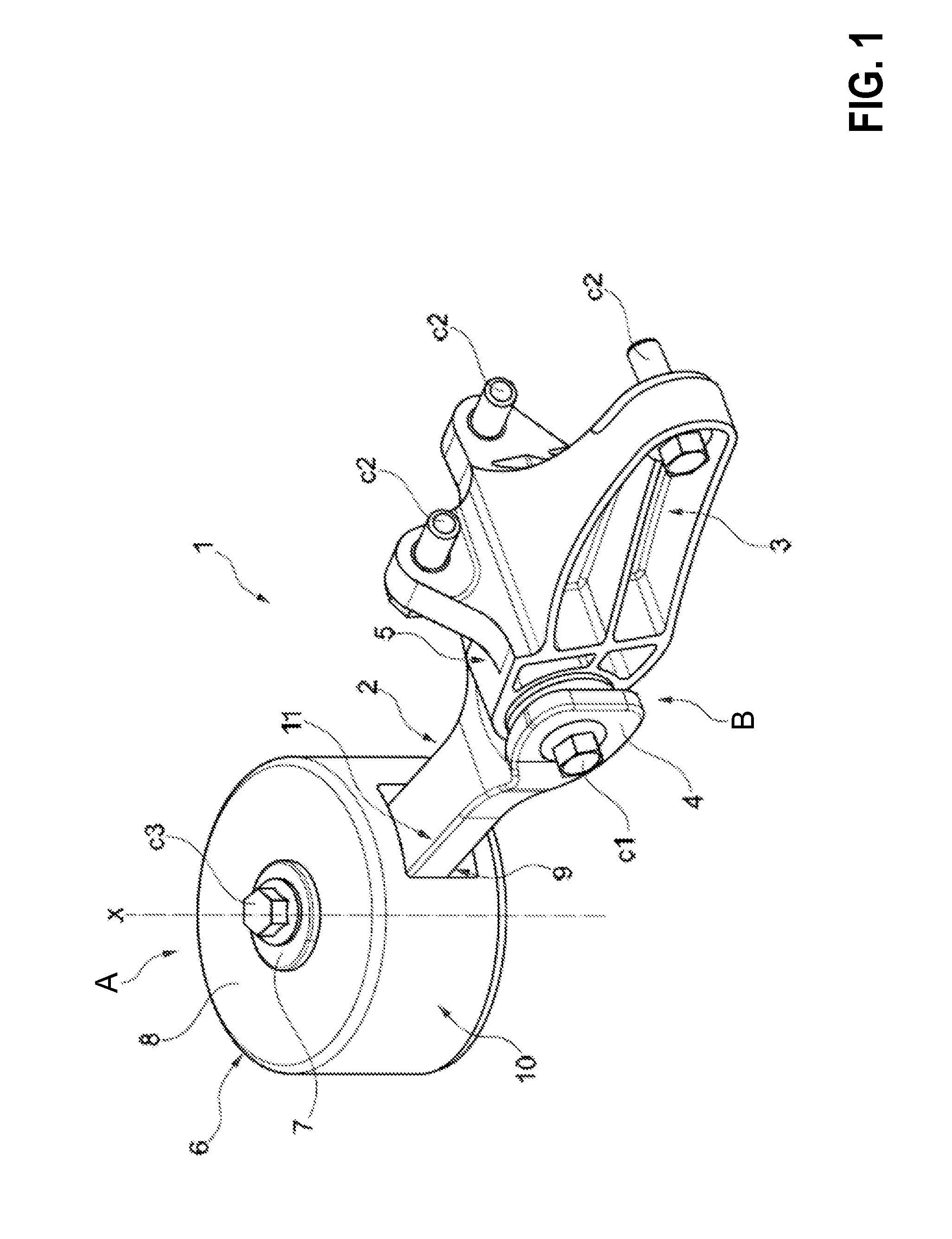
The patent proposes a way to reduce the number of parts and assembly time by using a single bearing core fitted within a single bearing bush. This also makes it easier to align and position the support member. By creating two core portions that can move relative to each other, an improved clamping action can be achieved which can reduce engine roll more effectively.

Problems solved by technology

Drive motors (or engines) may be prone to powerful pitch movements about drive shafts due to sudden changes in torque occurring during drive motor operation.
These larger openings may weaken the vehicle structure.
Herein, stabilization measures may be used to support the vehicle structure leading to an overall increase in the weight of the vehicle and an increase in production costs.
However, the inventors herein have identified potential issues with such an approach.
A larger number of components may add to the complexity of production and assembly, and may raise costs.

Method used


Image

  • System for reducing engine roll
  • System for reducing engine roll
  • System for reducing engine roll

Examples


Embodiment Construction

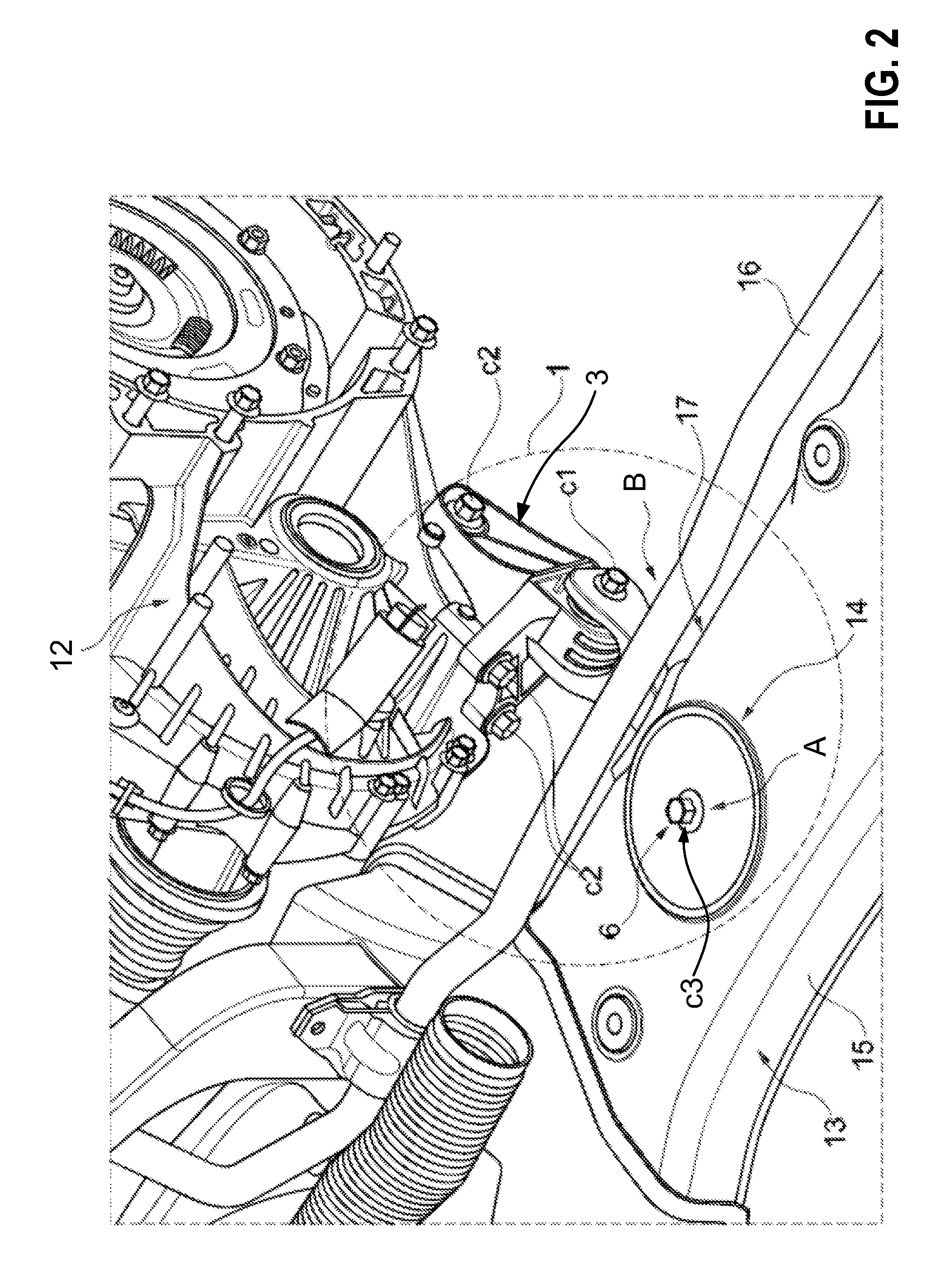
[0017]Drive motors used in vehicles may be operated with either fuel or electrical energy. In one example, drive motors may be a combination of an internal combustion engine and / or an electric motor with a gear mechanism. Drive motors may have a rotationally driven output shaft. The torque present at the output shaft may be transmitted to at least one drive wheel in road vehicles. By the wheel rolling on the ground, the rotational movement may be ultimately converted into a linear movement of the vehicle. However, sudden changes in torque produced during operation may result in occasional powerful pitch movements of the drive motor about the drive shaft. Differential torque present between previously produced torque and current torque may be responsible for pitch movements of the drive motor.

[0018]To reduce the effect of drive motor pitch movements, the drive motor may be supported on the vehicle structure at a region spaced perpendicularly apart from the drive shaft via a torque su...


PUM

PropertyMeasurementUnit
Heightaaaaaaaaaa
Torqueaaaaaaaaaa

Abstract

A system for an engine torque support is described comprising a support member connected to a vehicle structure at a first end via a bearing comprising a bearing core surrounded by a bearing bush. The bearing bush has a recess, and the bearing core includes a receiving channel for a connector, a notch extending transversely relative to the receiving channel, and a connection web formed in a plane of the notch creating a first core portion, and a second core portion of the bearing core. The second core portion is spaced apart from the first core portion by the notch, and the second core portion is displaced relative to the first core portion via resilient deformation of the connection web and / or via breaking of the connection web.

Description

CROSS REFERENCE TO RELATED APPLICATIONS[0001]The present application claims priority to German Patent Application No. 102013213077.5, filed on Jul. 4, 2013, the entire contents of which are hereby incorporated by reference for all purposes.TECHNICAL FIELD[0002]The present description relates to a torque support for a drive motor.BACKGROUND AND SUMMARY[0003]Drive motors (or engines) may be prone to powerful pitch movements about drive shafts due to sudden changes in torque occurring during drive motor operation. A torque support may reduce pitch movements of the drive motor by coupling the drive motor to the vehicle structure. However, larger openings may be required in the vehicle chassis structure to accommodate pivot bearings used by torque supports (e.g., extruded profile-section). These larger openings may weaken the vehicle structure. Herein, stabilization measures may be used to support the vehicle structure leading to an overall increase in the weight of the vehicle and an in...

Claims


Application Information

Patent Timeline
IPC IPC(8): B60K5/12F16F1/38
CPCB60K5/1241F16F2226/04F16F1/3821F16F1/3849Y10T29/49947
Inventor LOEFFELSENDER, MARKMEIER, CHRISTOPH
Owner FORD GLOBAL TECH LLC
Learn More