Conductivity inspection apparatus and conductivity inspection method

a conductivity inspection and conductivity technology, applied in the direction of instruments, final product manufacturing, sustainable manufacturing/processing, etc., can solve the problems of dragging and wounding the needle, not knowing whether or not the power is present, etc., to improve the reliability of inspection and reduce the generation of inspection failures

Active Publication Date: 2015-01-22
ENVISION AESC JAPAN LTD
View PDF3 Cites 4 Cited by
  • Summary
  • Abstract
  • Description
  • Claims
  • Application Information

AI Technical Summary

Benefits of technology

[0010]By the present invention, at least two needles are inserted. Accordingly, when one of the at least two needles is contacted on the metal foil, it is possible to inspect the conduction state. Consequently, it is possible to decrease the generation of the inspection failure, and to improve the reliability of the inspection, relative to a case in which the inspection is performed by one needle.

Problems solved by technology

Accordingly, when the needle is inserted from above on the surface of the laminate film, that is, the resin film, the needle may drag and wound the resin.
Consequently, it is not understand whether or not the power generation element and the aluminum foil of the laminate film are conducted with each other.

Method used


Image

  • Conductivity inspection apparatus and conductivity inspection method
  • Conductivity inspection apparatus and conductivity inspection method
  • Conductivity inspection apparatus and conductivity inspection method

Examples


first embodiment

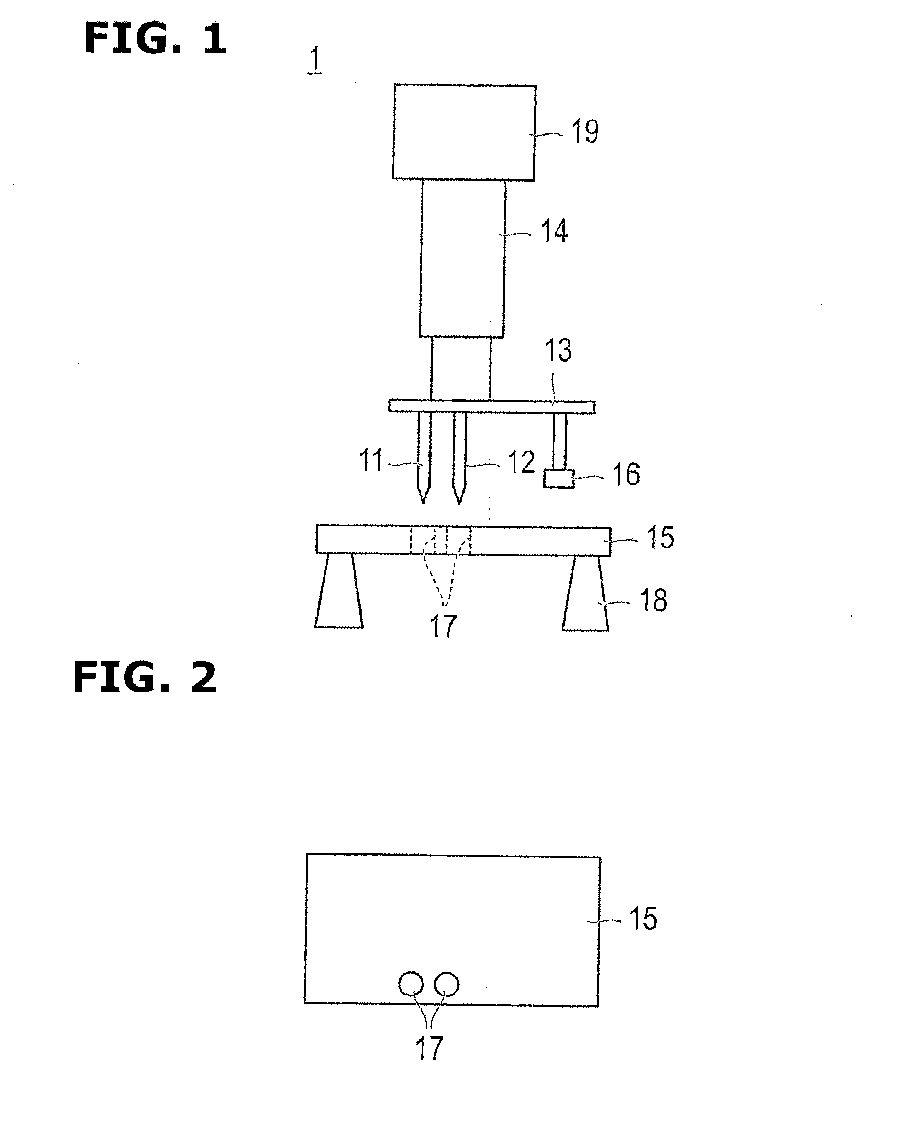
[0024]FIG. 1 is a schematic view for illustrating a conductivity inspection apparatus of a battery covered with a laminate film (an outer covering film) in a first embodiment.

[0025]This conductivity inspection apparatus 1 includes two conductive needles 11 and 12, a support portion (section) 13 integrally supporting the two needles 11 and 12, an air cylinder 14 arranged to move the support portion 13 in upward and downward directions, and a stage 15 holding the battery at a predetermined position. Moreover, the support portion (section) 13 is provided with an elastic pad 16 which is arranged to press tabs of the battery against the stage 15, at a position of the tabs of the battery which is mounted on the stage 15, as described below.

[0026]Two needles 11 and 12 are not specifically limited as long as the needles are conductive members such as a stainless, a copper, an iron, and other alloys. A tip end of each of the needles has acute angle. A middle portion (body portion) of each of...

second embodiment

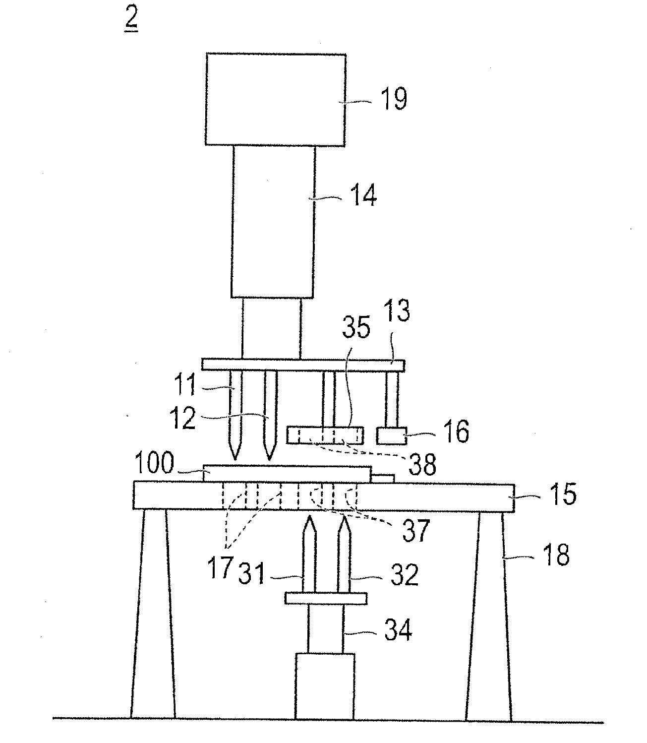
[0060]FIG. 9 is a schematic view for illustrating the conductivity inspection apparatus of the battery which is covered with the laminate film (outer covering film) in a second embodiment.

[0061]The conductivity inspection apparatus 2 according to the second embodiment is an apparatus in which a structure in which needles 31 and 32 are inserted from below is added to the structure in which the needles 11 and 12 are inserted from above in the first embodiment. That is, in a case where an upper side of the battery is a first surface and the lower side of the battery is a second surface, the needles 11 and 12, and 31 and 32 are inserted, respectively, from the first surface side, and the second surface side which is opposite to the first surface.

[0062]Accordingly, in the second embodiment, there are provided two needles 31 and 32 disposed below the stage 15, a lower support portion 33 which supports these needles 31 and 32, and a lower air cylinder 34 which moves the lower support porti...


PUM


Abstract

At least two needles (11, 12) are inserted from the surface of an outer covering film (200) such that the needles reach metal foils (252, 262) in the outer covering film (200), and the electrical connection state with an object inside of a structure covered with the outer covering film (200) is inspected. The electrical connection state is more reliably inspected.

Description

TECHNICAL FIELD[0001]This invention relates to a conductivity inspection apparatus and a method thereof, and more specifically to a conductivity inspection apparatus and a method thereof which are configured to inspect a conductive state of a to structural member covered by a film in which a metal foil is sandwiched between resin films.BACKGROUND ART[0002]In recent years, a laminate film (also referred to as a laminate sheet) is used as an outer covering member for covering a power generation element of a battery for decreasing a weight of the battery, and decreasing a thickness of the battery. The laminate film has, for example, a structure in which an aluminum foil is stacked between a resin film and a resin film.[0003]As a conduction (continuity) test method between this laminate film and the internal power generation element, there is a method of inserting a metal needle on a surface of the outer member of the laminate film, and measuring a resistance between this needle and a l...

Claims


Application Information

Patent Timeline
Patent Type & Authority Applications(United States)
IPC IPC(8): G01R1/067
CPCG01R1/0675G01R31/026G01R31/3627H01M10/0413H01M10/48H01M10/0436G01R31/385G01R31/54Y02E60/10Y02P70/50G01R19/145G01R31/50
Inventor MOTOHASHI, YUTAISHIBASHI, KEISHOTAKIMOTO, KIYOHIDEMIZUTA, MASATOMOTAKATSUKA, TAKUYA
Owner ENVISION AESC JAPAN LTD
Why Eureka
Try Eureka