
Wireless Entrance Communication Device

a communication device and wireless technology, applied in closed-circuit television systems, two-way working systems, television systems, etc., can solve problems such as limited placemen

Inactive Publication Date: 2015-01-22
BOT HOME AUTOMATION
View PDF11 Cites 184 Cited by
  • Summary
  • Abstract
  • Description
  • Claims
  • Application Information

AI Technical Summary

Benefits of technology

The device described in this patent has a camera, microphone, speaker, button, battery, and memory to store code. It also has a processor to activate when triggered, receive audio and video signals from the camera or microphone, and send signals to a server based on those signals. The device can also receive inbound audio and output it through the speaker. The device can also switch from active mode to low-power mode when triggered. The technical effect of this device is to allow for quick and effective communication with a camera and microphone, and the ability to switch between modes for more efficient use of battery power.

Problems solved by technology

Wireless intercom systems that use Wi-Fi communication require hard wiring to a power source and are thereby limited in placement.

Method used


Image

  • Wireless Entrance Communication Device
  • Wireless Entrance Communication Device
  • Wireless Entrance Communication Device

Examples


Embodiment Construction

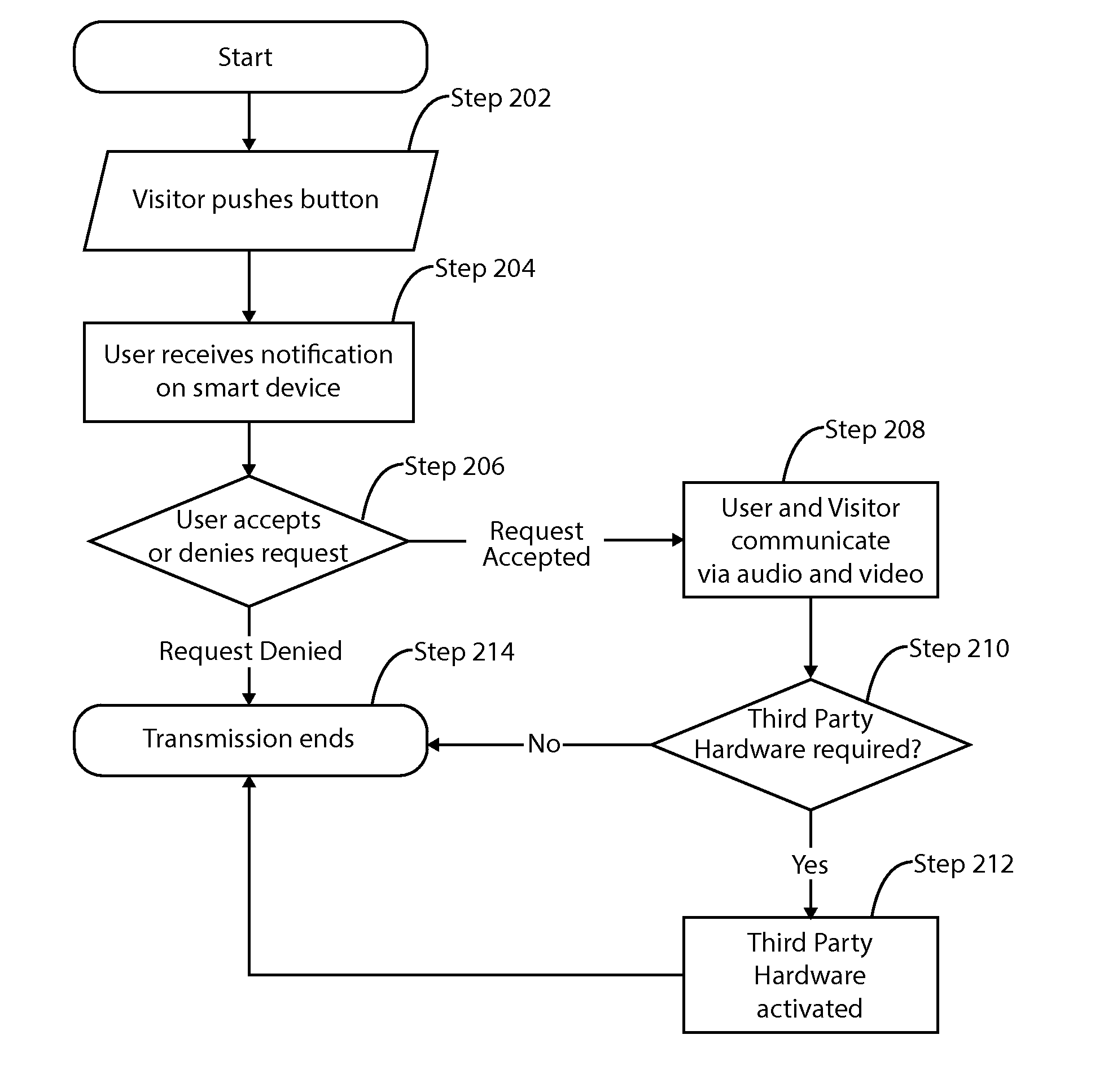
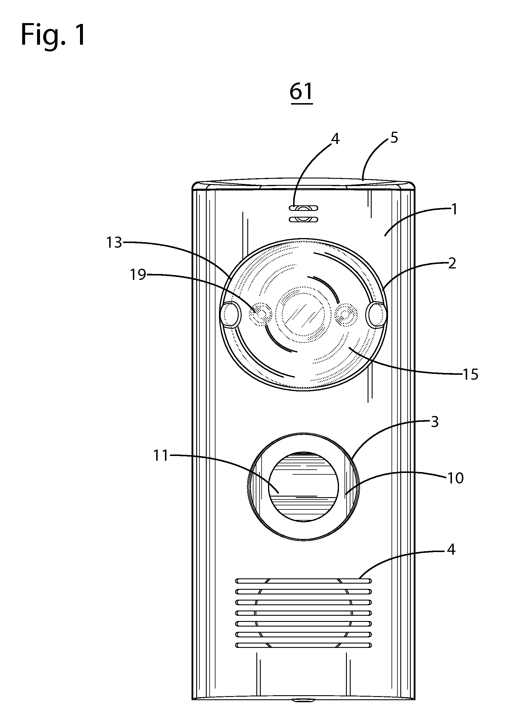
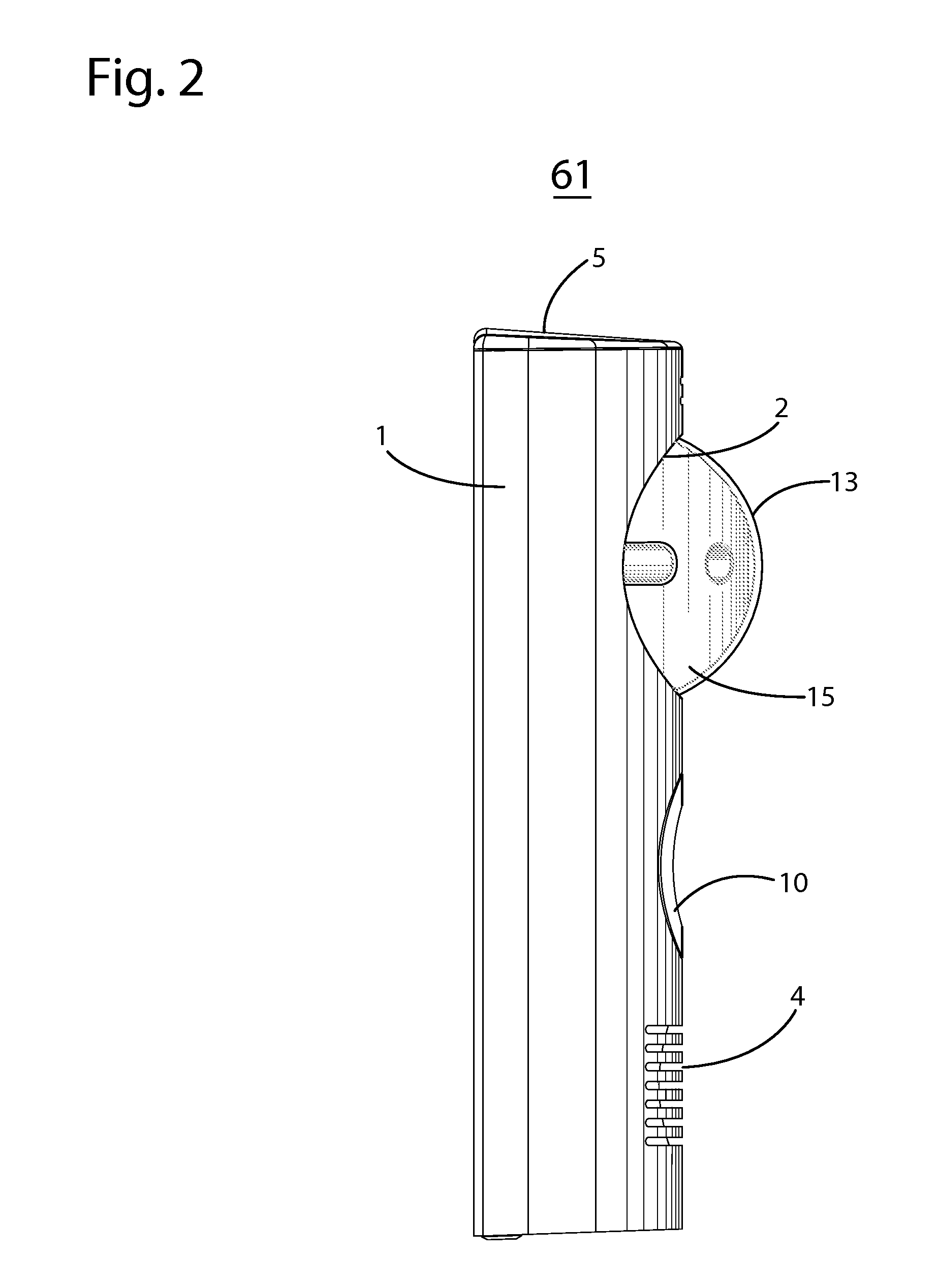
[0028]FIG. 1 shows a front view of the Wireless Communication Doorbell 61 according to an aspect of present disclosure. The Wireless Communication Doorbell 61 may have Faceplate 1 mounted to Housing 5. Faceplate 1 may be but not limited to brushed aluminum, stainless steel, wood or plastic. Faceplate 1 may contain Perforated Pattern 4 oriented to allow sound to travel in and out of Housing 5 to Microphone 21 and from Speaker 20. Faceplate 1 may be convex and include Button Aperture 3 to allow Button 11 and Light Pipe 10 to mount flush to Faceplate 1. Button 11 and Light Pipe 10 may have convex profiles to match the convex profile of Faceplate 1. Button 11 may be coupled to Housing 5 and may have a stem that protrudes through Housing 5, so Button 11 may make contact with Button Actuator 12 when Button 11 is pressed by Visitor 63. When Button 11 is pressed and makes initial contact with Button Actuator 12, Button Actuator 12 may activate or “wake” components within Wireless Communicat...


PUM


Abstract

A device for communicating including a housing including a camera, a microphone, a speaker, a button, a battery, non-volatile memory, a processor, and a wireless communications module, wherein the non-volatile memory stores code operable by the processor for switching the processor from low-power mode to active mode in response to an activation trigger, receiving, from the one of the microphone and the camera, outbound audio and video signals, then sending a signal to a server via the wireless communications module during active mode, the signal including one or more of an alert signal, a signal based on the outbound audio signal, and a signal based on the outbound video signal, receiving from the server an inbound audio signal and outputting a signal based on the inbound audio signal via the speaker, and switching the processor from active mode to low-power mode in response to a deactivation trigger.

Description

CROSS-REFERENCE TO RELATED APPLICATIONS[0001]This application claims the benefit of earlier filed U.S. Provisional Application No. 61 / 847,816, filed on Jul. 18, 2013, which is incorporated by reference herein in its entirety.BACKGROUND[0002]Home safety is a concern for many homeowners and renters. Those seeking to protect or monitor their homes often wish to have video and audio communications with visitors, for example, those visiting an external door or entryway. Existing wireless intercom systems require installation and configuration of multiple devices placed throughout the home that must operate together. Wireless intercom systems that use Wi-Fi communication require hard wiring to a power source and are thereby limited in placement. Therefore, it may be desirable to have a door monitor that may operate independently and consumes reduced energy.SUMMARY OF THE INVENTION[0003]A device for communicating including a housing including a camera, a microphone, a speaker, a button, a ...

Claims


Application Information

Patent Timeline
Patent Type & Authority Applications(United States)
IPC IPC(8): H04N7/18
CPCH04N7/186H04N21/4424
Inventor SIMINOFF, JAMES
Owner BOT HOME AUTOMATION
Learn More