Hybrid DC circuit breaking device

Inactive Publication Date: 2015-01-22
SIEMENS AG
View PDF8 Cites 49 Cited by
  • Summary
  • Abstract
  • Description
  • Claims
  • Application Information

AI Technical Summary

Benefits of technology

[0013]When a first varistor is connected in the tertiary current path so as to be in parallel with the serially connected switches and in parallel with the capacitor and a second varistor connected in the auxiliary current path, preferably the knee voltage of the second varist

Problems solved by technology

It may also be required that the main dc breaker be able to break the dc current in either dire

Method used


Image

  • Hybrid DC circuit breaking device
  • Hybrid DC circuit breaking device
  • Hybrid DC circuit breaking device

Examples


first embodiment

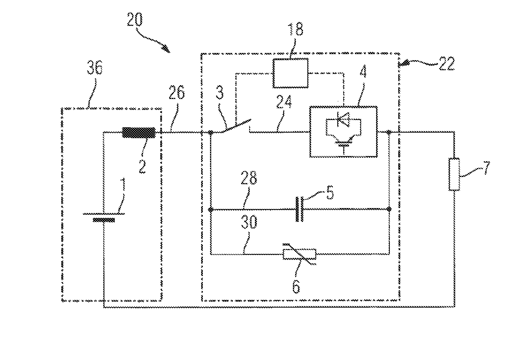
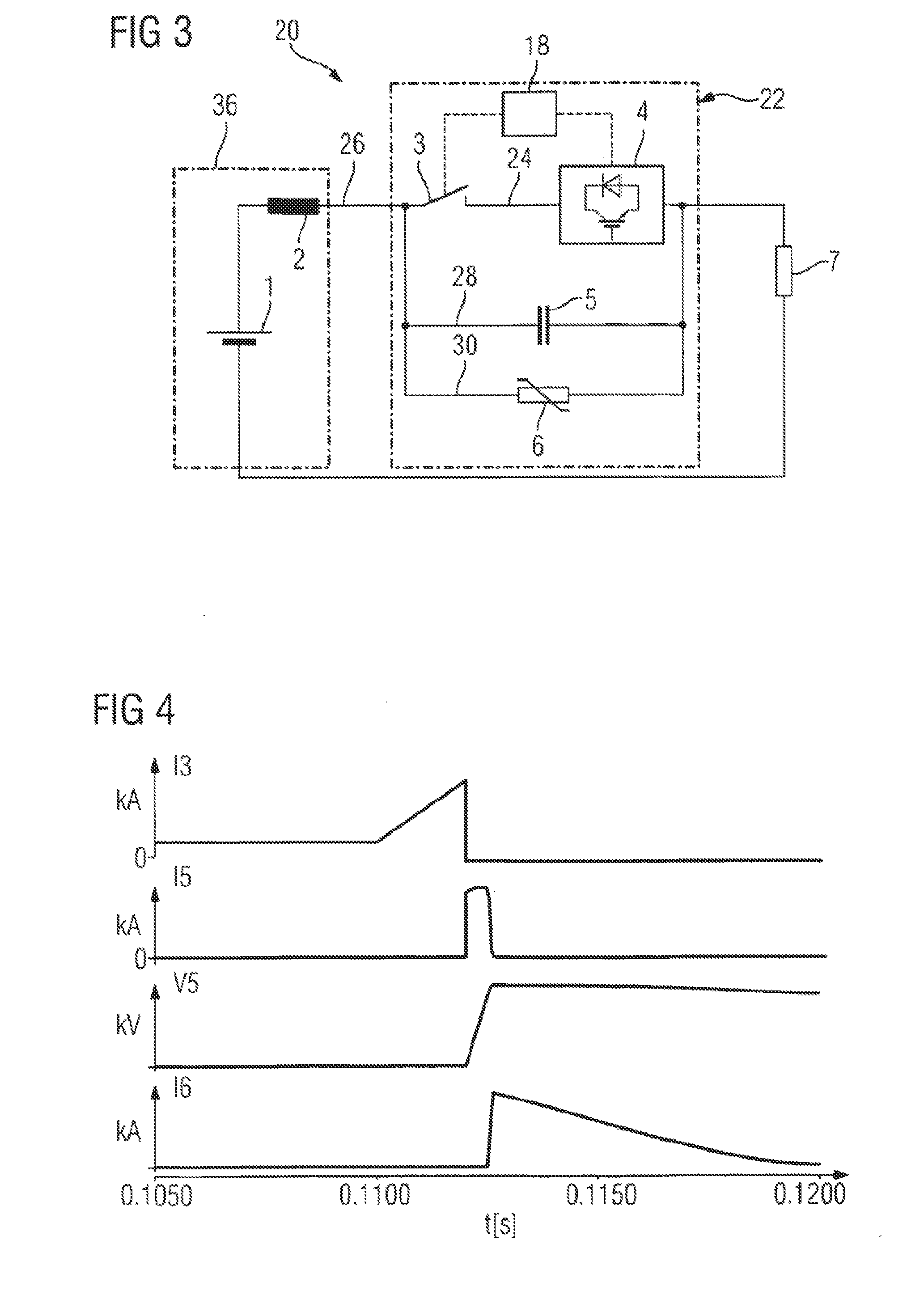
[0039]In FIG. 3, the device 20 further includes a tertiary current path 30 which is connected in parallel with the primary current path 24 and the secondary current path 28 and also forms part of the collective breaker circuit 22 connected in series with the main current path 26. In this instance, a first varistor 6 is connected in the tertiary current path so as to be parallel with the serially connected switches 3 and 4 and in parallel with the capacitor 5.

second embodiment

[0040] shown in FIG. 5, the device 20 also includes an auxiliary current path 32. In this instance, where the primary, secondary and tertiary current paths collectively define the breaker circuit 22 in series with the dc circuit 7, the auxiliary current path 32 is connected in parallel with the dc circuit 36. A second varistor 8 can then be connected in series with the auxiliary current path 32 so as to be connected in parallel with the main current path serially connecting the breaker circuit 22 and the dc circuit 7.

third embodiment

[0041] shown in FIG. 7, the device 20 includes all of the features of the previous embodiment together with an additional auxiliary current path 34 connected in parallel with the dc circuit 7. In this arrangement, the auxiliary current path 34 and parallel connected dc current 7 are collectively connected in series with the breaker circuit 22. A third varistor 9 is connected in series with the auxiliary current path 34 such that the third varistor is in parallel with the second dc circuit 7 and the collective parallel connection of the third varistor and the second dc circuit 7 is in series between the breaker circuit 22 and the return path of the second dc circuit 7 to the first dc circuit 36.


PUM


Abstract

A dc breaker is connected in a main current path between a first dc circuit and a second dc circuit. The dc breaker has a primary current path connected to the main current path. A mechanical interrupter switch and an electronic breaker switch are connected in series in the primary current path. A secondary current path is provided in parallel with the primary current path. A capacitor is arranged in the secondary current path so as to be connected in parallel with the series-connected switches of the primary current path.

Description

FIELD OF THE INVENTION[0001]The present invention relates to a hybrid type dc circuit breaking device comprising a breaker circuit having serially connected mechanical and electronic switches and a capacitor in parallel with the serially connected switches; and more particularly the present invention relates to possible use of the breaker circuit in combination with one or more varistors to stop or allow the flow of dc current in an electric circuit. Moreover, this invention comprises the fast discharge circuit to allow for fast reclose of the dc breaker.BACKGROUND[0002]A prior art Hybrid dc Circuit breaker as shown in FIG. 1 is described in the publication “Protective Hybrid HVdc Breakers—A Key Innovation for Reliable HVdc Grids,” by Jurgen Hafner and Bjorn Jacobson in CIGRE International Symposium, Bologna, Italy, Sept. 13-15, 2011, which is incorporated herein by reference. More particularly in the publication a hybrid dc breaker is disclosed consisting of a mechanical fast disco...

Claims


Application Information

Patent Timeline
IPC IPC(8): H02H1/00H02H3/08
CPCH02H1/0007H02H3/08H02H3/087H01H9/548H01H33/596
Inventor MOHADDES, KHORASSANI, MOJTABA
Owner SIEMENS AG
Why Eureka
Try Eureka