
Direct current (DC) breaker topology structure and DC breaker control method

A technology of DC circuit breaker and topology structure, which is applied to high-voltage air circuit breakers, circuits, and high-voltage/high-current switches, etc., can solve the problems of increasing equipment cost, control complexity, and the number of fully-controlled power electronic devices. Good energy absorption and overvoltage suppression effect, low cost and cost reduction effect

Inactive Publication Date: 2015-09-09
NORTH CHINA ELECTRIC POWER UNIV (BAODING)
View PDF9 Cites 27 Cited by
  • Summary
  • Abstract
  • Description
  • Claims
  • Application Information

AI Technical Summary

Problems solved by technology

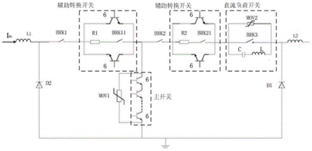
However, its DC circuit breaker is to realize two-way flow and two-way cut-off, and the two auxiliary transfer switches adopt an anti-parallel structure composed of two fully-controlled power electronic devices 6, and are respectively connected with the series resistance R1 and the isolation switch BRK11, The resistor R2 in series and the isolating switch BRK21 are connected in parallel, so the number of fully-controlled power electronic devices is doubled; in the case of low current and voltage stress such as opening and closing for maintenance, the resistor R1 and the isolating switch BRK11, resistor The soft opening circuit composed of R2 and isolation switch BRK21, and the DC load switch composed of arrester MOV2, AC circuit breaker BRK3, inductance L and capacitor C significantly increase the equipment cost and control complexity

Method used


Image

  • Direct current (DC) breaker topology structure and DC breaker control method
  • Direct current (DC) breaker topology structure and DC breaker control method
  • Direct current (DC) breaker topology structure and DC breaker control method

Examples


Embodiment Construction

[0057] The present invention proposes a topology structure of a DC circuit breaker and a control method thereof. The technical content of the present invention will be further described in detail below in conjunction with the accompanying drawings.

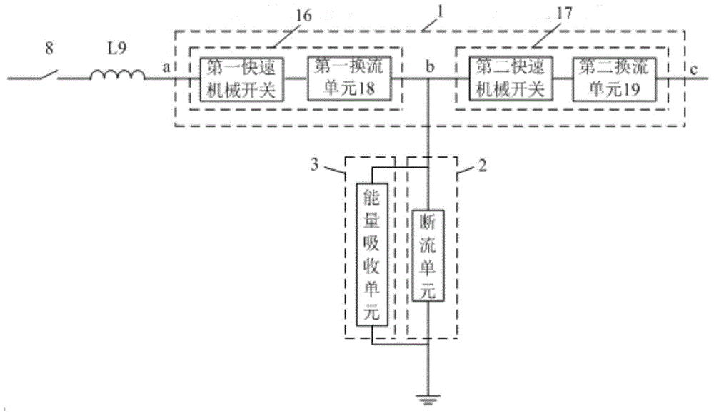
[0058] image 3 A schematic diagram of the DC circuit breaker topology provided by the present invention. image 3 Among them, the topological structure of the DC circuit breaker adopts a "T-shaped" bidirectional symmetrical structure; the DC circuit breaker of the "T-shaped" bidirectional symmetrical structure is composed of a first current path 1, a second current path 2 and a third current path 3 , the second current path 2 and the third current path 3 are connected in parallel to the midpoint of the first current path 1 connected in a bidirectional symmetrical T-shaped structure; the lead-out terminal a of the first current path 1 is connected to the DC power transmission and distribution system One end of the equivalent indu...


PUM


Abstract

The invention discloses a DC breaker topology structure and a DC control method and belongs to the field of power and electronic technologies. The DC breaker has a "T" type two-way symmetrical structure and comprises a first current path, a second current path and a third current path. A leading-out terminal a of the first current path is connected with an end of a DC power transmission and distribution system equivalent inductor L9. A middle leading-out terminal b of the first current path is connected with one parallel ends of the second current path and the third current path. A leading-out terminal c of the first current path is connected with a DC power transmission and distribution line. The other parallel ends of the second current path and the third current path are connected with the ground. The invention can effectively solve the problem of DC arc extinguishing, is flexible in structure and strong in expansibility, meets the requirements of current switching on, current switching off, voltage endurance, loss, energy absorption and the like under different voltage and current levels of the DC power transmission and distribution grid, and significantly reduces the equipment cost.

Description

technical field [0001] The invention belongs to the technical field of power electronics, and in particular relates to a topology structure of a DC circuit breaker for DC transmission and a control method thereof, in particular to a topology scheme and a control strategy of a DC circuit breaker of a high-performance and low-cost DC transmission and distribution network. Background technique [0002] DC circuit breaker is a key equipment for carrying rated current, shutting off fault current, and shutting off load current in DC transmission and distribution networks. It can reliably clear fault current and prevent the expansion of fault range. With the rapid development of multi-terminal DC transmission technology, smart grid and DC distribution network technology, distributed power supply and DC micro-grid technology, DC circuit breakers are of great significance to the reliable, high-quality and economical operation of the power grid. However, the arc extinguishing problem ...

Claims


Application Information

Patent Timeline
IPC IPC(8): H01H33/59
CPCH01H33/596
Inventor 黄永章卫思明
Owner NORTH CHINA ELECTRIC POWER UNIV (BAODING)
Learn More