
Direct current circuit breaker and circuit breaking method for direct current power transmission system

A technology of DC circuit breaker and circuit breaker body, which is applied in the direction of electrical components, power transmission AC network, emergency protection circuit device, etc., can solve problems such as DC transmission network constraints, achieve short action time, solve ablation problems, and limit short circuits The effect of current

Inactive Publication Date: 2017-03-22
CHINA ELECTRIC POWER RES INST +3
View PDF3 Cites 26 Cited by
  • Summary
  • Abstract
  • Description
  • Claims
  • Application Information

AI Technical Summary

Problems solved by technology

[0005] In order to overcome the above problems, the present invention provides a DC circuit breaker and a DC transmission system disconnection method, taking into account the advantages of small on-state loss of mechanical circuit breakers and rapid action of all solid-state circuit breakers, which can adapt to the high voltage and high current of future DC power grids The development needs of the DC transmission network are solved due to the factor of the circuit breaker and the problem of being restricted by the development

Method used


Image

  • Direct current circuit breaker and circuit breaking method for direct current power transmission system
  • Direct current circuit breaker and circuit breaking method for direct current power transmission system
  • Direct current circuit breaker and circuit breaking method for direct current power transmission system

Examples


Embodiment Construction

[0022] In order to further explain the technical means and effects of the present invention to achieve the intended purpose of the invention, the specific implementation, structure, features and effects of the present invention will be described in detail below in conjunction with the accompanying drawings and preferred embodiments.

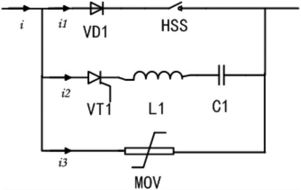
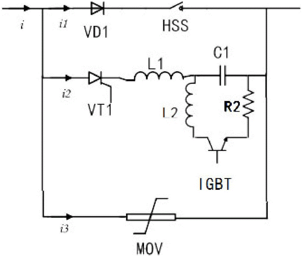
[0023] figure 1 Shown is the topological structure diagram of the first embodiment of the present invention. See figure 1 , the DC circuit breaker of this embodiment is used to control the on-off of the high-voltage direct current transmission system, including a control system, a parallel current-through circuit, an LC forced transfer circuit, and a protection branch;

[0024] The control system is used to control the on-off of the current-through circuit and the LC forced transfer circuit. The current-through circuit is composed of the circuit breaker body HSS and the power diode VD1 in series; the LC forced transfer circuit is composed of the...


PUM


Abstract

The invention provides a direct current circuit breaker used for controlling on-off of a high-voltage direct current power transmission system. The direct current circuit breaker comprises a control system, a protection branch, and a through-flow circuit and an LC forced transfer circuit which are in parallel connection, wherein the through-flow circuit consists of a circuit breaker body and an electric power diode which are connected in series; the LC forced transfer circuit consists of a first pre-charging capacitor, a first inductor and a thyristor which are connected in series; the response time of the thyristor is shorten than that of the circuit breaker body; the protection branch is used for performing voltage clamping when the voltages at the two ends of the through-flow circuit and / or the LC forced transfer circuit are greater than or equal to a voltage set value; the control system is used for controlling the on-off of the through-flow circuit and the LC forced transfer circuit; and the control system is used for transmitting a conduction signal to the thyristor before the circuit breaker body is disconnected so as to enable the current passing through the through-flow circuit to be lower than or equal to a first current set value at the disconnecting moment of the circuit breaker body.

Description

technical field [0001] The invention relates to the field of circuit breakers, in particular to a DC circuit breaker and a circuit breaking method for a DC transmission system. Background technique [0002] In recent years, due to the low cost of the DC system, no capacitive current, no eddy current loss, and easier control of the power flow, the DC HVDC transmission system has attracted much attention. Especially in some specific occasions, such as large-scale ship power supply system, urban rail transit power supply system and other DC systems have been greatly developed. At the same time, with the continuous increase of the capacity of the DC system and the continuous improvement of the voltage level, the peak value of the short-circuit current can reach more than 100kA, and the rate of increase of the short-circuit current is also more than 15A / us. Traditional mechanical circuit breakers are difficult to adapt to the development needs of high voltage and high current in...

Claims


Application Information

Patent Timeline
IPC IPC(8): H02H7/22H02J3/36
CPCH02H7/22H02J3/36Y02E60/60
Inventor 李金忠高飞冯英徐征宇王琳郭佳豪张书琦徐丹赵晓宇崔彧菲赵志刚段嘉炜孙建涛易强汪可
Owner CHINA ELECTRIC POWER RES INST
Learn More