System and method for monitoring power applied to a bicycle

a technology for monitoring power and bicycles, applied in the field of sensor devices, can solve the problems of no devices known in the art that determine power, and achieve the effect of optimizing speed and endurance, fast, easy and accura

Active Publication Date: 2015-01-22
MEDHAB
View PDF6 Cites 38 Cited by
  • Summary
  • Abstract
  • Description
  • Claims
  • Application Information

AI Technical Summary

Benefits of technology

[0027]Another objective is to provide a sensor system that enables the calculation of power exerted while riding a bicycle, without requiring any changes to the bicycle, or installation of sensors in or on the pedals of the bicycle.
[0028]Another objective is to provide a method of calculating power using the sensor system described herein, or an equivalent system, that is fast, easy, and accurate.
[0029]Another objective is to provide a sensor system that is able to output various forms of data regarding the person's activities on the bicycle, such as cadence, average power, average maximum power, and other data, so that the person can receive, in real time, information to assist him or her in accomplishing his or her objectives during the ride.
[0030]Another objective is to provide a sensor system that is able to assist the person in his or her training, to optimize his or her speed and endurance.

Problems solved by technology

There are no devices known in the art that determine power while riding a bicycle, which are mounted in the shoes of the user.

Method used


Image

  • System and method for monitoring power applied to a bicycle
  • System and method for monitoring power applied to a bicycle
  • System and method for monitoring power applied to a bicycle

Examples


Embodiment Construction

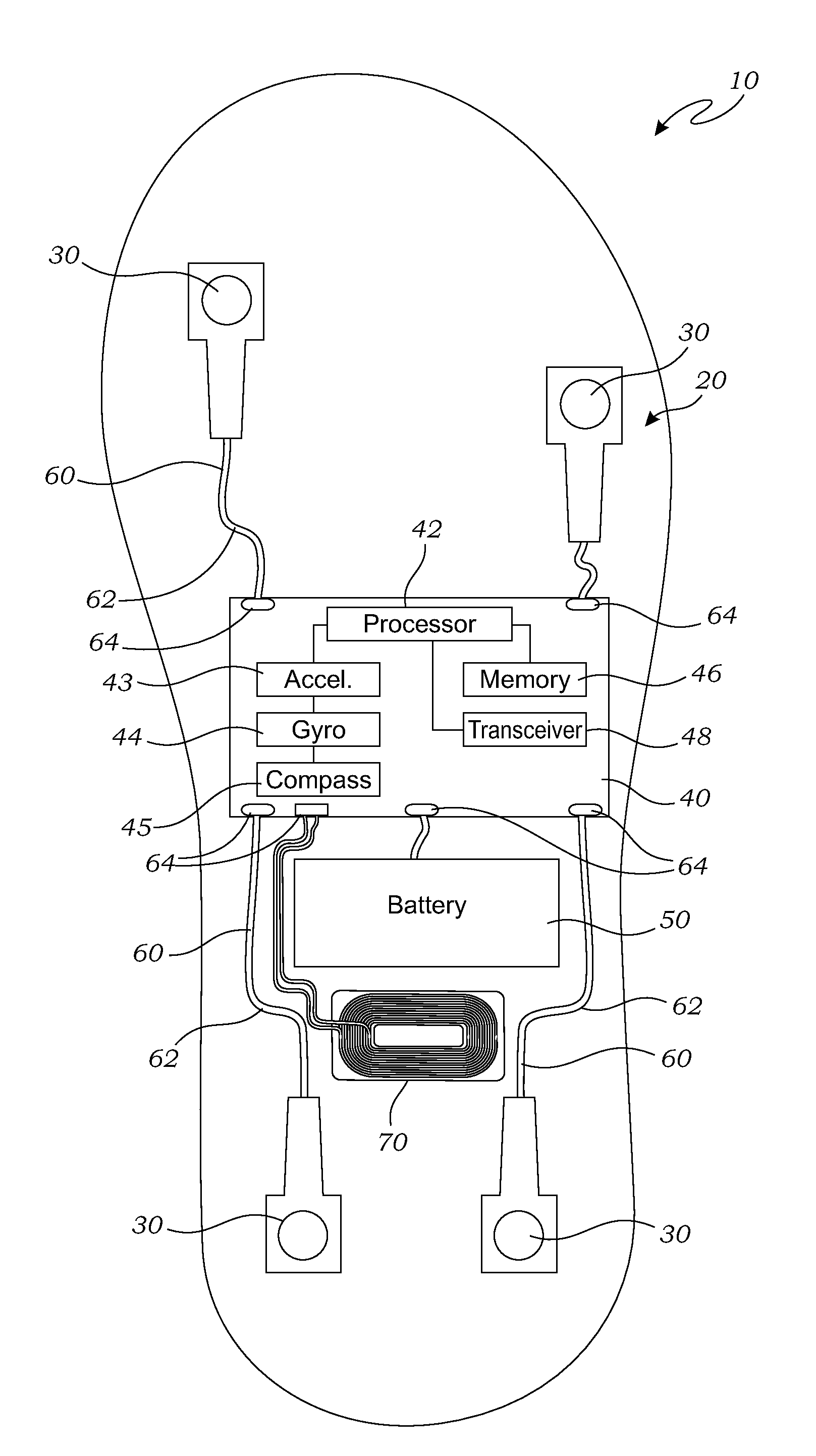
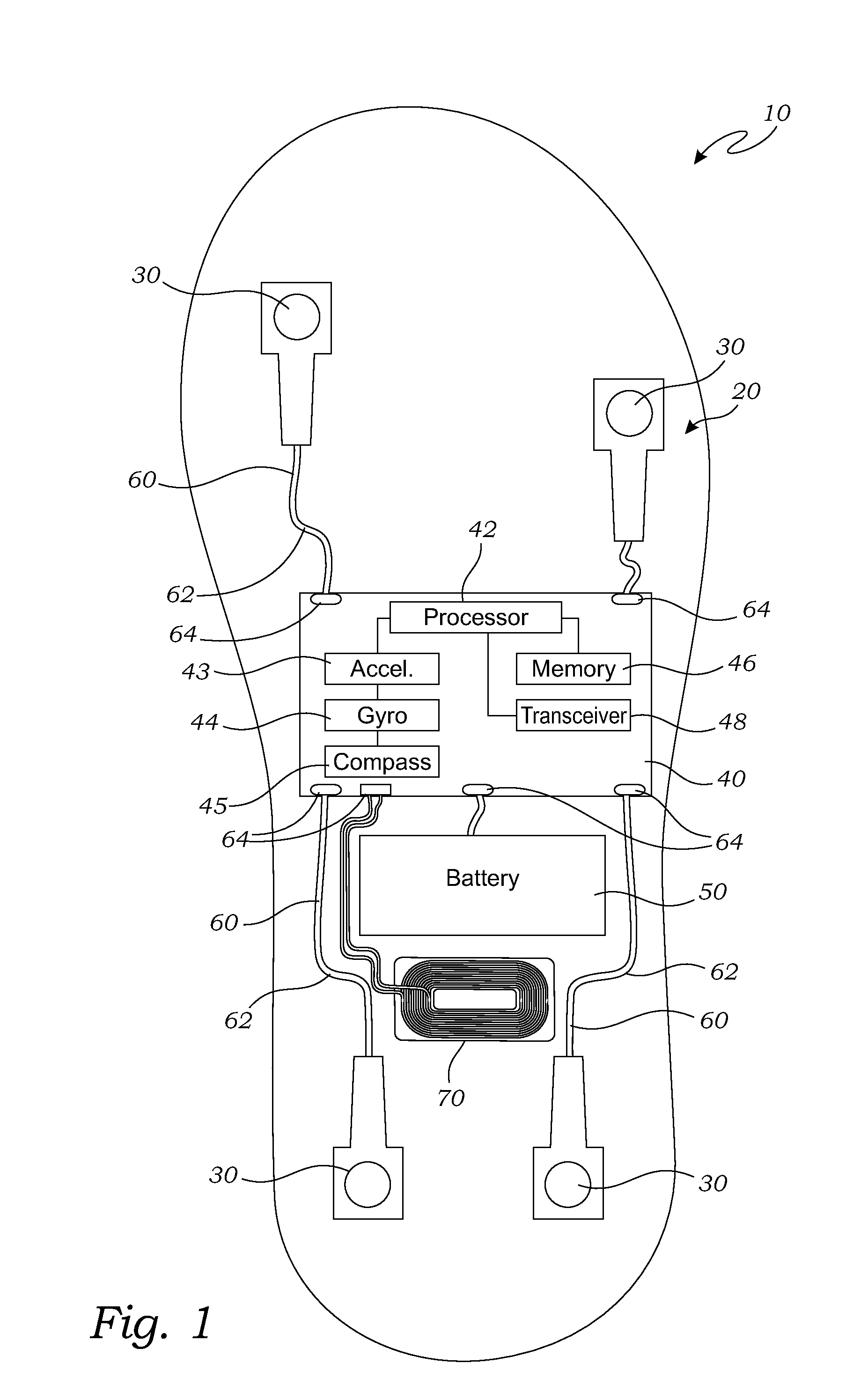
[0056]FIG. 1 is a block diagram of a sensor insole 10, according to one embodiment of the present invention. A felt layer, discussed below, is removed in this view to more clearly show a sensor assembly 20 that is located within the sensor insole 10.

[0057]As illustrated in FIG. 1, the sensor insole 10 is shaped and adapted to fit within a shoe of a user (not shown), or otherwise positioned against the underside of the foot of the user. The sensor assembly 20 is mounted on the sensor insole 10 for monitoring various forces and conditions of the sensor insole 10, in this embodiment the sensor assembly 20 includes force sensors 30. In the embodiment of FIG. 1, the sensor insole 10 may include a printed circuit board (“PCB”) 40 having (or being operably attached to a computer processor 42, a computer memory 46, a battery 50, and the force sensors 30. The force sensors 30 may be any form of sensors useful for sensing force that are known in the art. While four of the force sensors 30 are...


PUM

PropertyMeasurementUnit
timeaaaaaaaaaa
power measurementaaaaaaaaaa
forceaaaaaaaaaa

Abstract

A sensor system and method for monitoring power exerted by a person riding a bicycle has a pair of sensor insoles and a portable electronic device. The sensor insoles each have a plurality of force sensors, an accelerometer, and a transmitter for transmitting data from the plurality of force sensors and the accelerometer. A power measurement program operably installed in the computer memory of the portable electronic device receives the data and calculates power and other outputs based upon the data received.

Description

CROSS-REFERENCE TO RELATED APPLICATIONS[0001]This application for a utility patent is a continuation-in-part of the following previously filed utility patent applications: application Ser. No. 14 / 217,337, still pending, filed Mar. 17, 2014; application Ser. No. 13 / 749,665, still pending, filed Jan. 24, 2013; application Ser. No. 13 / 741,294, still pending, filed Jan. 14, 2013; and application Ser. No. 13 / 070,649, now U.S. Pat. No. 8,384,551, filed Mar. 24, 2011.[0002]This application for a utility patent also claims the benefit of the following U.S. Provisional Application Nos. 61 / 800,981, filed Mar. 15, 2013; 61 / 867,064, filed Aug. 17, 2013; and 61 / 889,878, filed Oct. 11, 2013.BACKGROUND OF THE INVENTION[0003]1. Field of the Invention[0004]This invention relates generally to sensor devices, and more particularly to a shoe-mounted sensor device for monitoring the movements of a person's feet, and the forces exerted upon the user's foot, to determine power exerted by the person.[0005]...

Claims


Application Information

Patent Timeline
Patent Type & Authority Applications(United States)
IPC IPC(8): G01L1/26G01P7/00A63B24/00G01L3/24
CPCA63B24/0062G01L1/26A63B2220/51G01L3/24A63B2220/00G01P7/00A61B2562/0219A61B5/1038G01L25/00A61B5/6807G01L5/00A61B5/11A61B5/6811A61B2562/12A61B2562/0247Y10T29/49128A43B3/0005A61B5/743A43B5/14A43B17/00A43B3/34
Inventor ROSS, JOHNNY
Owner MEDHAB
Why Eureka
Try Eureka