
Electrically powered motorized vehicle with continuously variable transmission and combined hybrid system

a technology of electric motors and hybrid systems, applied in the field of electric vehicles and hybrid drive systems, can solve the problems of inability to overcome the fixed transmission ratio of electrical the requirement of long hours for charging batteries, and the various problems of electricly powered motor vehicles, so as to maximize efficiency and speed. the effect of power and speed optimization

Inactive Publication Date: 2011-02-24
ANANTHAKRISHNA ANIL
View PDF4 Cites 32 Cited by
  • Summary
  • Abstract
  • Description
  • Claims
  • Application Information

AI Technical Summary

Benefits of technology

[0008]It is a primary object of the present invention to describe an electric vehicle with hybrid drive system, which provides optimization of speed, power and maximizing efficiency levels.

Problems solved by technology

On the other hand, electrically powered motorized vehicles suffer from various disadvantages such as requirement of long hours for charging a battery, ability to run only on battery power and so on.
The electrically powered motorized vehicles have fixed transmission ratio that is not capable of overcoming varying gradients over which the vehicle might be traversing and at the same time provide high speeds.
Also, by drawing heavy currents from the batteries, the entire system might be made to work under reduced efficiency yielding much lesser battery life.

Method used


Image

  • Electrically powered motorized vehicle with continuously variable transmission and combined hybrid system
  • Electrically powered motorized vehicle with continuously variable transmission and combined hybrid system
  • Electrically powered motorized vehicle with continuously variable transmission and combined hybrid system

Examples


Embodiment Construction

[0018]The preferred embodiments of the present invention will now be explained with reference to the accompanying drawings. It should be understood however that the disclosed embodiments are merely exemplary of the invention, which may be embodied in various forms. The following description and figures are not to be construed as limiting the invention and numerous specific details are described to provide a thorough understanding of the present invention, as the basis for the claims and as a basis for teaching one skilled in the art about making and / or using the invention. However in certain instances, well-known or conventional details are not described in order not to unnecessarily obscure the present invention in detail.

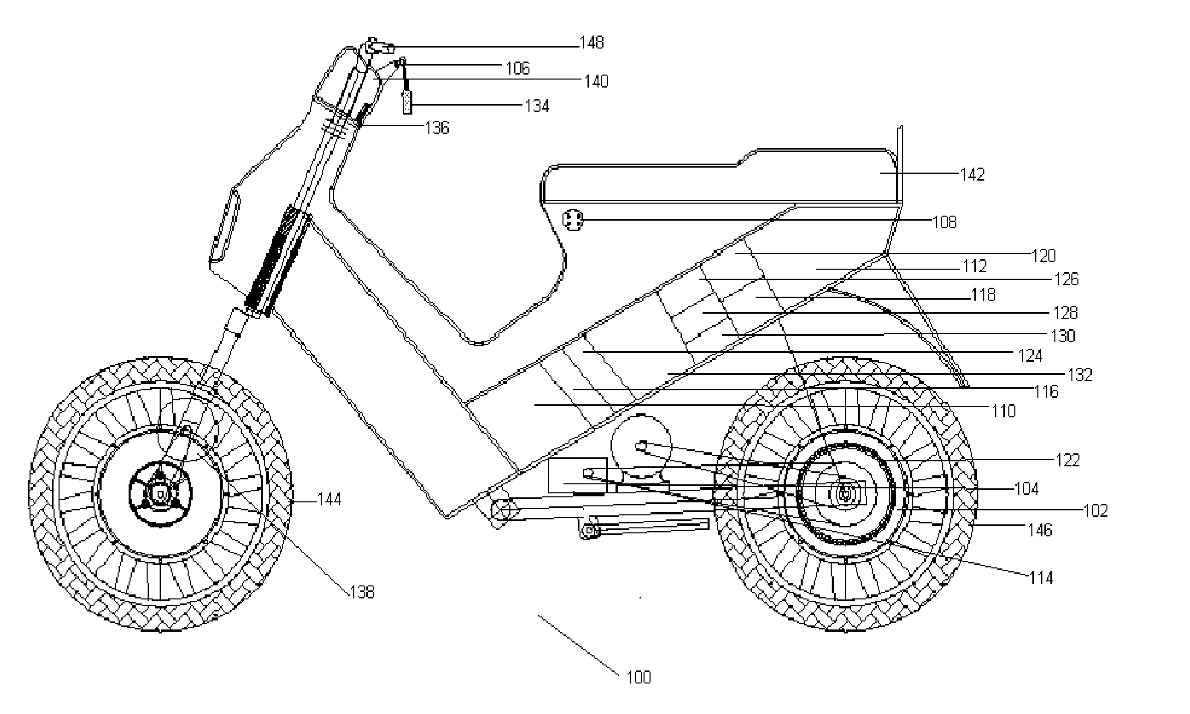
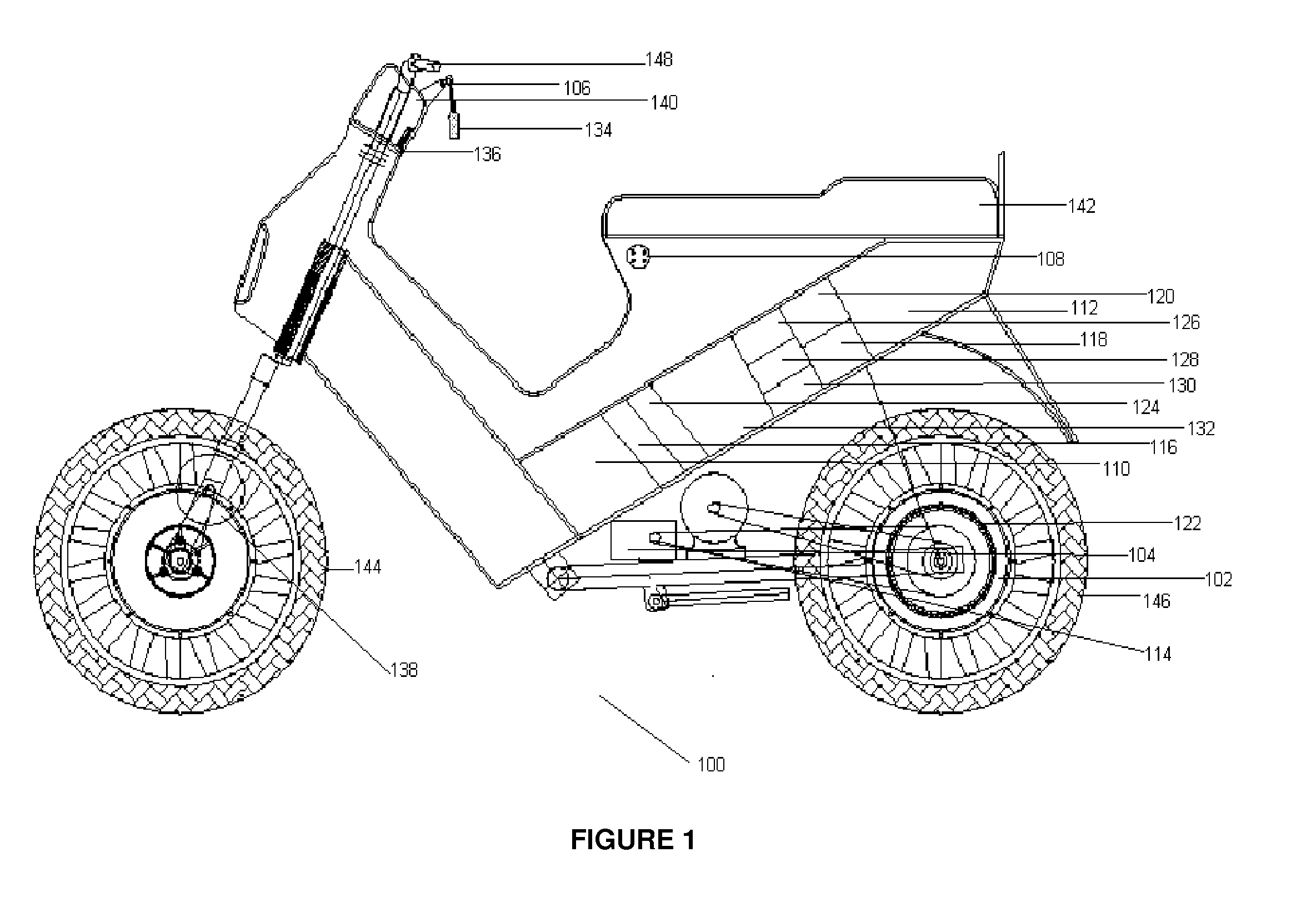
[0019]FIG. 1 is a schematic side view of an electric vehicle with a hybrid drive system, in accordance with the present invention. Particularly, the electric vehicle (100) includes a hybrid drive system. In one embodiment, the hybrid drive system includes an elect...


PUM


Abstract

The present invention describes an electric vehicle with hybrid drive system, which provides optimization of speed, power and maximizing efficiency levels. In one embodiment, the vehicle includes at least one driven wheel, an electric motor connected to the driven wheel through a fixed transmission system or a continuous variable transmission (CVT) unit, an internal combustion engine (ICE) connected to the driven wheel through a fixed transmission system or a CVT unit and a selector switch to select the modes of power supply to the electric vehicle. Further, the electric motor is powered by a battery power pack and the ICE is powered by a hydrocarbon fuels stored in a hydrocarbon fuel tank. Furthermore, the different position of selector switch provides different modes of the power supply to the vehicle. In another embodiment, the electric motor is adapted to be operated as a generator.

Description

RELATED APPLICATION[0001]Benefit is claimed under 35 U.S.C. 119(e) to U.S. Provisional Application Ser. No. 61 / 151,831, entitled “ELECTRICALLY POWERED MOTORIZED VEHICLE WITH CONTINUOUSLY VARIABLE TRANSMISSION AND COMBINED HYBRID SYSTEM” by Anil Ananthakrishna, filed on Feb. 11, 2009, which is herein incorporated in its entirety by reference for all purposes.FIELD OF THE INVENTION[0002]The present invention generally relates to the field of automobiles. Particularly, the present invention relates to an electric vehicle. More particularly, the present invention relates to a hybrid drive system in an electric vehicle which provides optimization of power and efficiency.BACKGROUND OF THE INVENTION[0003]Motorized vehicles have become very popular especially for personal transport purpose. Motorized bikes in particular provide a riding experience similar to that of a non motorized, pedal powered bicycle, but without the manual exertion. Accordingly, individuals with limited physical stamin...

Claims


Application Information

Patent Timeline
Patent Type & Authority Applications(United States)
IPC IPC(8): B60W20/00H02J7/00B60K6/48B60W10/06B60W10/08
CPCB60K6/12Y02T90/121B60K6/48B60K6/543B60L11/14B60L11/185B60L11/1862B60L2200/12B60L2220/16B60W10/06B60W10/08B60W10/26B60W20/00B60Y2200/12B60Y2400/15B62K11/10B62K2202/00B62K2204/00Y02T10/6208Y02T10/6221Y02T10/6269Y02T10/6278Y02T10/6282Y02T10/6286Y02T10/7005Y02T10/7044Y02T10/705Y02T10/7077Y02T90/128Y02T90/14B60L11/007Y02T10/70B60K6/28B60W2050/146B60L50/16B60L50/20B60L53/11Y02T10/62Y02T10/7072B60W20/20Y02T90/12
Inventor ANANTHAKRISHNA, ANIL
Owner ANANTHAKRISHNA ANIL
Learn More