Flexible roll forming device, blank guide device, blank feeding device, and flexible roll forming system having the same

a flexible, roll-forming technology, applied in the direction of metal-working feeding devices, conveying devices, manufacturing tools, etc., can solve the problem of not being able to form beams having different widths and heights along the length direction of the beam

Active Publication Date: 2015-01-29
SUNG WOO HITECH
View PDF13 Cites 15 Cited by
  • Summary
  • Abstract
  • Description
  • Claims
  • Application Information

AI Technical Summary

Benefits of technology

[0039]An exemplary embodiment of the present invention can allow roll forming of a 3D formed beam having a modified cross-section with different widths and heights along a length direction of a blank having a straight portion, an expanded portion, and so on by configuring a multi-stage roll forming device for varying axis direction positions and angles of the upper and lower forming rolls.
[0040]Eventually, vehicle body members, frames, and beams having cross-sectional profiles of which widths and heights are different from one another along the length direction can be roll formed as one unit with one roll forming event, permitting minimization of following steps, such as welding, jointing, and the like, contributing to manufacture of lighter cars.

Problems solved by technology

However, in view of the nature of the roll forming with the related art roll forming units, it has a drawback in that only formation of beams having a fixed cross-section along the length direction of the beams is possible, and formation of beams having different widths and heights along the length direction thereof is not possible.
Consequently, since formation of products of different modified cross-sections having different widths and heights along the length direction cannot be formed with the roll forming method, the products have been formed by applying multi-stage forming with a non-continuous process and long cycle time.

Method used


Image

  • Flexible roll forming device, blank guide device, blank feeding device, and flexible roll forming system having the same
  • Flexible roll forming device, blank guide device, blank feeding device, and flexible roll forming system having the same
  • Flexible roll forming device, blank guide device, blank feeding device, and flexible roll forming system having the same

Examples


Embodiment Construction

[0055]Hereinafter, an exemplary embodiment of the present invention will be described with reference to the accompanying drawings.

[0056]A thickness or a size of an element shown in a drawing can be exaggerated, omitted, or shown schematically for convenience or clarity of description.

[0057]Parts not relevant to the description are omitted for clarity of the description of an exemplary embodiment of the present invention, and the same or similar elements will be given identical reference numerals throughout the specification.

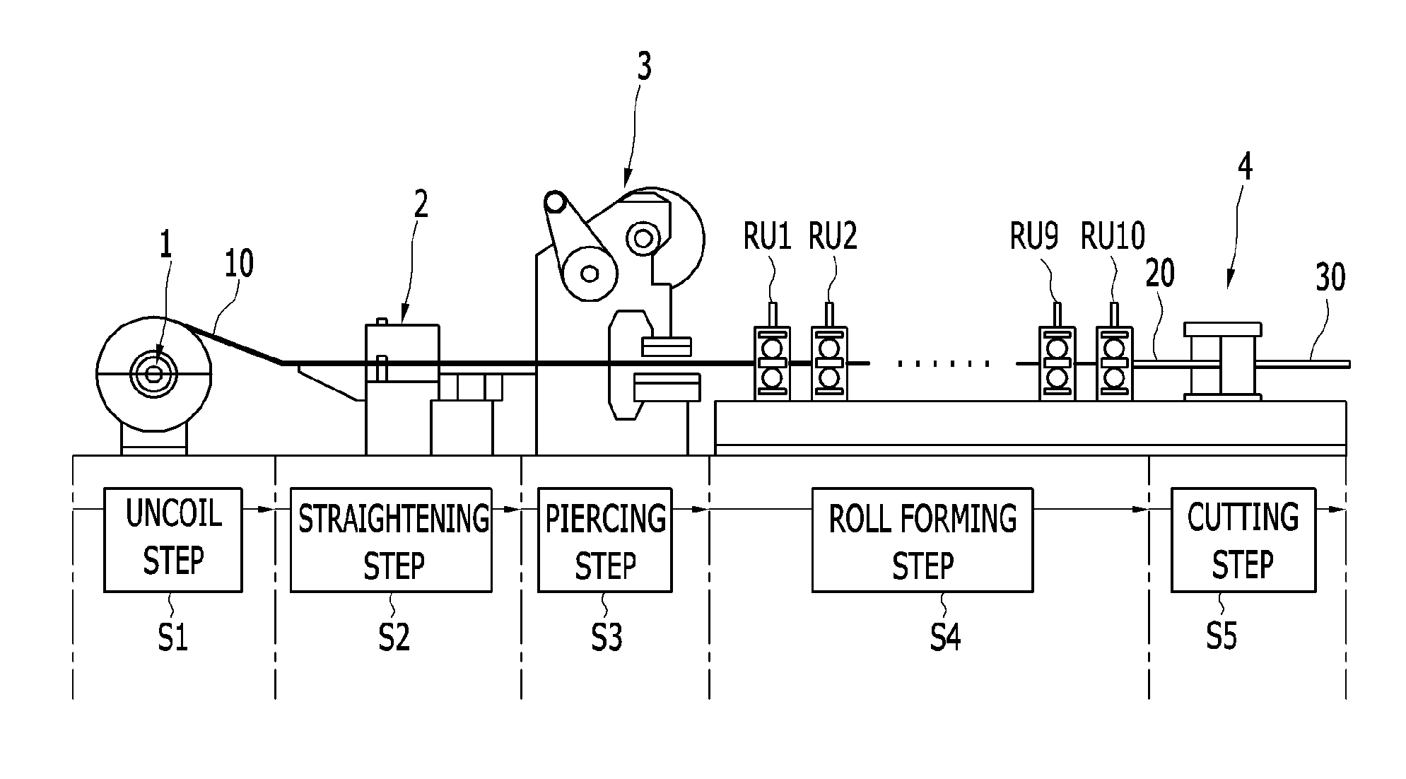
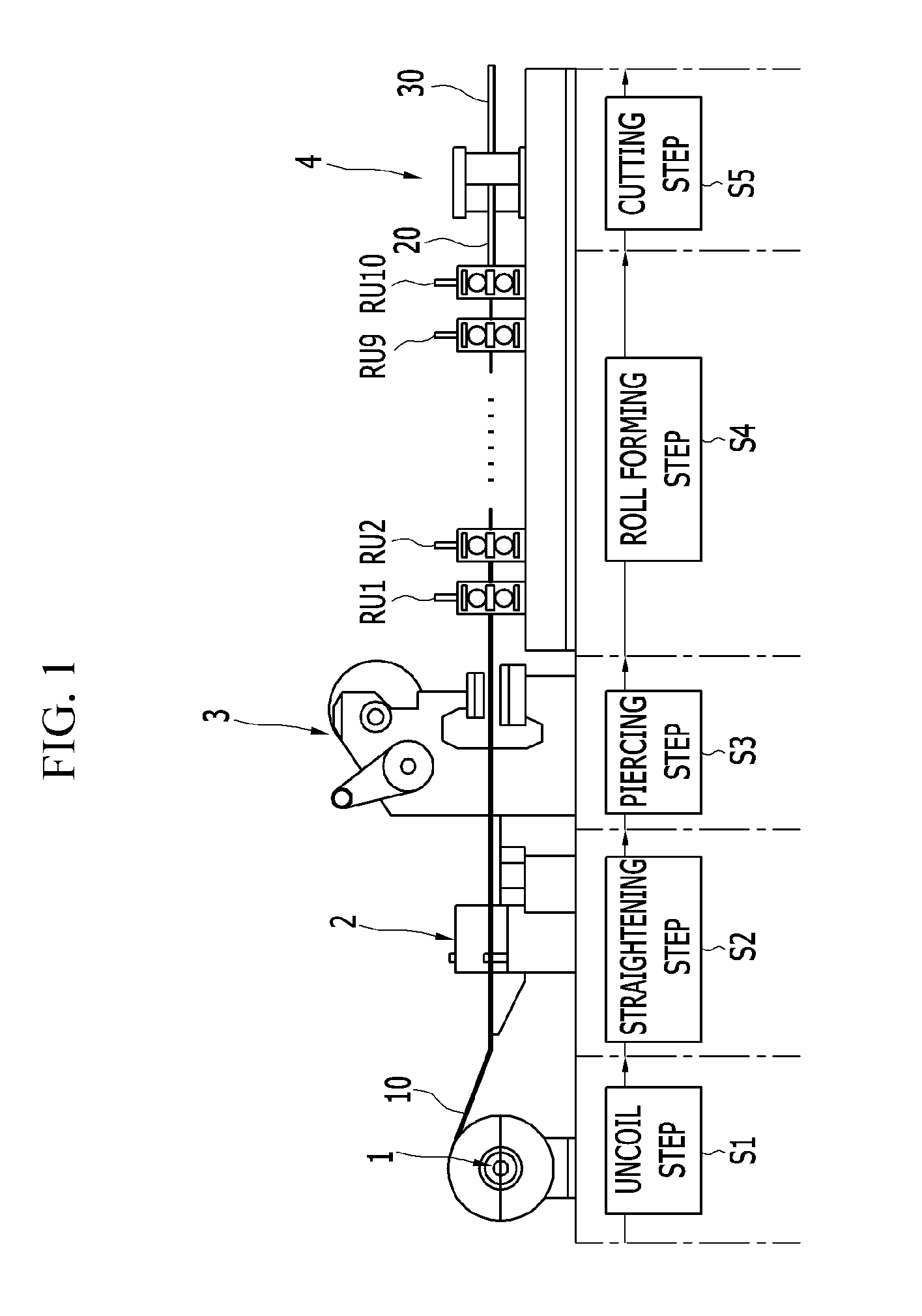
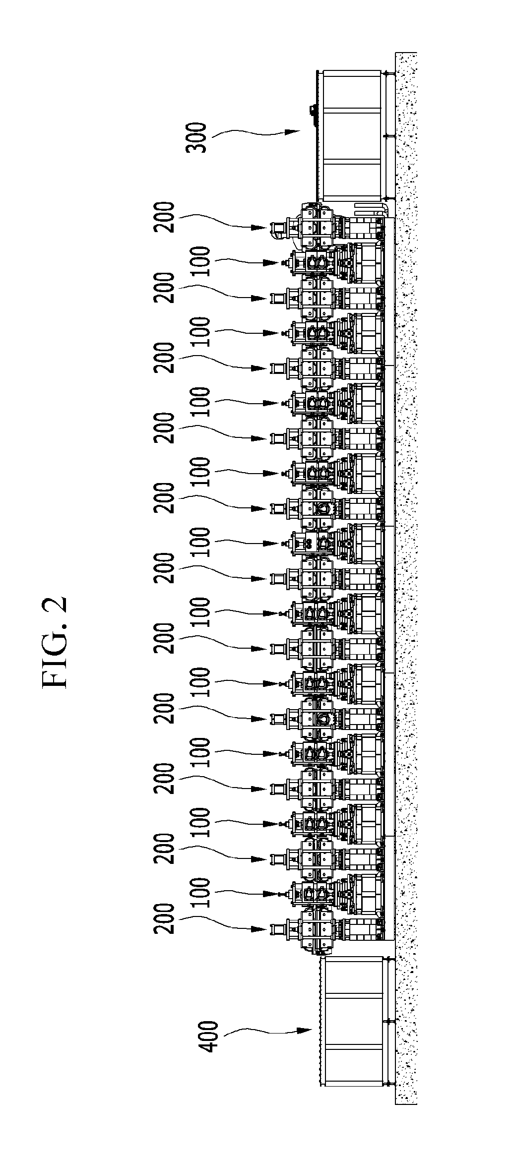
[0058]FIG. 2 illustrates a schematic view of a flexible roll forming system showing a concept of steps in accordance with an exemplary embodiment of the present invention.

[0059]Referring to FIG. 2, basically, the flexible roll forming system in accordance with an exemplary embodiment of the present invention uses a blank or a piece as a material (hereinafter, blank) thereof rather than a coil material.

[0060]Hereinafter, a process direction is a path in which the ...


PUM

PropertyMeasurementUnit
flexibleaaaaaaaaaa
torqueaaaaaaaaaa
rotation forceaaaaaaaaaa

Abstract

Disclosed is a flexible roll forming device including: bases respectively disposed on opposite sides with respect to a process direction center line in a left / right direction, each having an opening formed in an upper side thereof connected to an inside thereof, and rails configured thereon on opposite sides of the opening in a lateral direction of the process; forward / backward moving means having a slide plate provided to be movable along the rails on the base; turning means rotatably provided to the slide plate; and roll forming means provided on the turning means to include upper and lower forming rolls for subjecting a material fed thereto to flexible roll forming by using the upper and lower forming rolls while varying positions in the lateral direction of processing with the forward / backward moving means, and angles from a process direction with the turning means.

Description

CROSS-REFERENCE TO RELATED APPLICATION[0001]This application claims priority to and the benefit of Korean Patent Application Nos. 10-2013-0088295, 10-2013-0088297, 10-2013-0088302, and 10-2013-0088305 filed in the Korean Intellectual Property Office on Jul. 25, 2013, the entire contents of which are incorporated herein by reference.BACKGROUND OF THE INVENTION[0002](a) Field of the Invention[0003]The present invention relates to a flexible roll forming system. More particularly, the present invention relates to a flexible roll forming device for subjecting a blank material to roll forming of a formed beam having different widths and heights along a length direction, a material guide device, a material feeding device, and a flexible roll forming system having the same.[0004](b) Description of the Related Art[0005]In general, roll forming is a method including uncoiling a material coil and passing it through multi-stages of roll forming units each having one pair of an upper roll and a...

Claims


Application Information

Patent Timeline
Patent Type & Authority Applications(United States)
IPC IPC(8): B21B31/20B65G13/11B21B39/14B21B1/22B21B35/00
CPCB21B31/20B21B1/22B65G13/11B21B39/14B21B35/00B65G21/2072B21D5/08B21D5/083B21D5/12B21D43/003B21D43/006B21D43/055
Inventor LEE, MUN YONGJUNG, JIN HO
Owner SUNG WOO HITECH
Why Eureka
Try Eureka